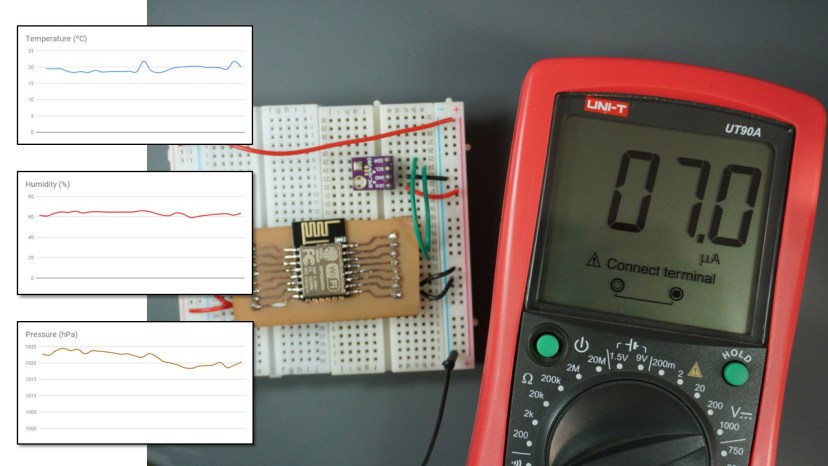
This project shows how to build a data logger that publishes temperature, humidity and pressure readings every 10 minutes to a Google Sheets spreadsheet using an ESP8266 12-E. Between sensor readings the ESP is in deep sleep mode and only consumes 7μA. The ESP board is programmed using MicroPython and we use the IFTTT Webhooks service to integrate the project with Google sheets.
This project is also compatible with the ESP32. You just have to make a few modifications in the code (we’ll show you what you need to do).
Throughout this project, you’ll learn the following concepts:
- Read temperature, humidity and pressure with the BME280 and ESP8266/ESP32 using MicroPython;
- Make HTTP post requests in MicroPython to send sensor readings to a third-party service;
- Use IFTTT Webhooks services to save sensor readings in a Google Sheets spreadsheet;
- Put the ESP8266/ESP32 in deep sleep mode and wake it up with a timer;
- Learn more about deep sleep in MicroPython:
MicroPython Firmware
To follow this tutorial you need MicroPython firmware flashed in your ESP32 or ESP8266. You also need an IDE to write and upload the code to your board. We suggest using Thonny IDE or uPyCraft IDE:
- Thonny IDE:
- uPyCraft IDE:
- Install uPyCraft IDE (Windows, Mac OS X, Linux)
- Flash/Upload MicroPython Firmware to ESP32 and ESP8266
Creating Your IFTTT Account
In this project we’ll publish sensor readings in a Google Sheets spreadsheet. To do that, we’ll use IFTTT Webhooks services. So, you need to create a free account on IFTTT.
Go the official site ifttt.com, enter your email and complete your account to get started.

Creating an Applet
Next, you need to create a new Applet. Follow the next steps to create a new Applet:
1) Go to “My Applets“and create a new Applet by clicking the “New Applet” button.

2) Click on the “this” word that is in a blue color – as highlighted in the figure below.

3) Search for the “Webhooks” service and select the Webhooks icon.

4) Choose the “Receive a web request” trigger.

5) Give a name to the event. In this case, we’ll be using “bme_280_readings” and we recommend using that exact same event name as shown in the figure below. After that, click the “Create trigger” button.

6) Click the “that” word to proceed.

7) Search for the “Google Sheets” service, and select the Google Sheets icon.

8) If you haven’t connected with the Google Sheets service yet, you need to click the “Connect” button.

9) Choose the “Add a row to spreadsheet” action.

10) Then, complete the action fields. Give the spreadsheet a name, and leave the other fields as default. Finally, click the “Create action” button.

11) Your Applet should be created after you press the “Finish” button.

Testing Your Applet
Before proceeding with the project, it is very important to test your applet first. Follow the next steps to test your Applet.
1) Go to the Webhooks Service page, and click the “Documentation” button.

2) A page as shown in the following figure will appear. The page shows your unique API key. You shouldn’t share your unique API key with anyone.
Fill the “To trigger an Event” section as shown below – it is highlighted with red rectangles. Then, click the “Test it” button.

Note: save your IFTTT API key because you’ll need it later in this project.
3) The event should be successfully triggered, and you’ll get a green message as shown below saying “Event has been triggered“.

4) Go to your Google Drive. The IFTTT service should have created a folder called “IFTTT” with the “MakerWebooks/bme280” folder inside. Inside this folder, you’ll find the Bme_280_readings spreadsheet.

5) Open the spreadsheet. You should have the values you’ve filled previously to test the Applet.

Continue reading this tutorial to see how to integrate the IFTTT Google Sheets service with your ESP8266 or ESP32.
Parts Required
Here’s a list of parts you need to build the circuit for this project:
- ESP8266 12-E – read Best ESP8266 Wi-Fi Development Boards
- ESP8266 12-E adapter
- FTDI programmer
- [Alternative] ESP32 board – read ESP32 development boards comparison
- BME280 sensor module
- [Optional] Voltage regulator circuit for LiPo and Li-ion batteries
- Jumper wires
- Breadboard
For this project we’ll be using the ESP8266 12-E because it consumes less power in deep sleep mode (it doesn’t have a built-in programmer). You can also use an ESP8266 NodeMCU Kit or an ESP32 development board.
You can use the preceding links or go directly to MakerAdvisor.com/tools to find all the parts for your projects at the best price!

Uploading Code to the ESP8266 12-E Chip
Uploading code to the ESP-12E requires establishing a serial communication between your ESP8266 and an FTDI Programmer as shown in the schematic diagram below.

- RX – TX
- TX – RX
- VCC – VCC
- VCC – EN
- GND – GND
- GND – GPIO15
- GND – GPIO0
If you want to learn more about the ESP12-E pins and how to use them, you can read our ESP8266 Pinout Reference Guide.
Installing the BME280 library
The library to read from the BME280 sensor isn’t part of the standard MicroPython firmware. So, you need to upload the library to your ESP8266/ESP32 board.
In uPyCraft IDE, create a new file by pressing the New File button (1). Copy the BME280 library code into it. The BME280 library code can be found in the following link:
Save the file by pressing the Save button (2).

Call this new file “BME280.py” and press ok.

Click the Download and Run button.
![]()
Note: if you’re having trouble uploading a new script to your ESP board, you might need to re-flash the MicroPython firmware on your board: Flash/Upload MicroPython Firmware to ESP. When the ESP is in deep sleep mode, you can’t upload new scripts. Make sure you reset your board, press the Stop button in uPyCraft IDE immediately to catch it awake, so you can access the saved scripts and upload new ones.
The file should be saved on the device folder with the name “BME280.py” as highlighted in the figure below.

Now, you can use the library functionalities in your code by importing the library.
Code
After uploading the BME280.py file to your ESP8266 or ESP32, copy the following code to the boot.py file. The boot.py file runs once on boot (it means every time the ESP8266/ESP32 wakes up).
# Complete project details at https://RandomNerdTutorials.com
import machine
from machine import Pin, I2C

import BME280
import network
import urequests
from time import sleep

import esp
esp.osdebug(None)

import gc
gc.collect()

ssid = 'REPLACE_WITH_YOUR_SSID'
password = 'REPLACE_WITH_YOUR_PASSWORD'

api_key = 'REPLACE_WITH_YOUR_IFTTT_API_KEY'

ms_sleep_time = 600000

station = network.WLAN(network.STA_IF)

station.active(True)
station.connect(ssid, password)

while station.isconnected() == False:
  pass

print('Connection successful')
print(station.ifconfig())

def deep_sleep(msecs) :
  # configure RTC.ALARM0 to be able to wake the device
  rtc = machine.RTC()
  rtc.irq(trigger=rtc.ALARM0, wake=machine.DEEPSLEEP)

  # set RTC.ALARM0 to fire after X milliseconds (waking the device)
  rtc.alarm(rtc.ALARM0, msecs)

  # put the device to sleep
  machine.deepsleep()

# ESP8266 - Pin assignement
i2c = I2C(scl=Pin(5),sda=Pin(4), freq=10000)

# ESP32 - Pin assignement
#i2c = I2C(scl=Pin(22),sda=Pin(21), freq=10000)

try:
  bme = BME280.BME280(i2c=i2c)
  temp = bme.temperature
  hum = bme.humidity
  pres = bme.pressure

  # uncomment for temperature in Fahrenheit
  #temp = (bme.read_temperature()/100) * (9/5) + 32
  #temp = str(round(temp, 2)) + 'F'

  sensor_readings = {'value1':temp[:-1], 'value2':hum[:-1], 'value3':pres[:-3]}
  print(sensor_readings)

  request_headers = {'Content-Type': 'application/json'}

  request = urequests.post(
    'http://maker.ifttt.com/trigger/bme280/with/key/' + api_key,
    json=sensor_readings,
    headers=request_headers)
  print(request.text)
  request.close()

except OSError as e:
  print('Failed to read/publish sensor readings.')

sleep(10)

#ESP8266
deep_sleep(ms_sleep_time)

#ESP32
#machine.deepsleep(ms_sleep_time)
Before uploading the code to your board, you need to include your own network credentials and your unique IFTTT API key. Continue reading to see how to do that.
How the Code Works
Let’s take a quick look at the code and see how it works.
Importing libraries
You start by importing the necessary modules. To interact with the GPIOs and read data from the sensor via I2C communication, you need to import the Pin and I2C classes from the machine module. You also import the complete machine module to be able to use functions related with deep sleep.
import machine
from machine import Pin, I2C
You need to import the BME280 library that you previously uploaded to the board.
import BME280To connect to your network, you need to import the network module.
import networkYou need the urequests library. This library allows you to make HTTP requests. In this example, we’ll make a request to the IFTTT services to publish the sensor readings to a Google Sheets spreadsheet.
import urequestsFinally, import thesleep function from the time module to be able to add delays to the code.
from time import sleepSetting your network credentials
You need to add your SSID and password in the following variables:
ssid = 'REPLACE_WITH_YOUR_SSID'
password = 'REPLACE_WITH_YOUR_PASSWORD'
Including your IFTTT API key
Insert your unique API key from the Webhooks IFTTT service in the following line:
api_key = 'REPLACE_WITH_YOUR_WEBHOOKS_IFTTT_API_KEY'Setting the sleep time
In this example we’ve set the sleep time to 10 minutes (600000 milliseconds). This means that every 10 minutes the ESP wakes up, takes the readings, and publishes them in your Google Sheets spreadsheet. The sleep time is set in the ms_sleep_time variable in milliseconds:
ms_sleep_time = 600000Warning: if you set a very short period, you may exceed the limit of requests imposed by the IFTTT services.
Connecting to the network
The following lines connect the ESP8266/ESP32 to your router, and print the ESP IP address:
station = network.WLAN(network.STA_IF)

station.active(True)
station.connect(ssid, password)

while station.isconnected() == False:
  pass

print('Connection successful')
print(station.ifconfig())
Deep sleep function (ESP8266)
Then, create a function called deep_sleep() that accepts as argument the number of milliseconds we want the ESP8266 to be in deep sleep mode.
def deep_sleep(msecs) :
  # configure RTC.ALARM0 to be able to wake the device
  rtc = machine.RTC()
  rtc.irq(trigger=rtc.ALARM0, wake=machine.DEEPSLEEP)

  # set RTC.ALARM0 to fire after X milliseconds (waking the device)
  rtc.alarm(rtc.ALARM0, msecs)

  # put the device to sleep
  machine.deepsleep()
Note: if you’re using an ESP32, you don’t need to create/use this function.
Reading temperature, humidity, and pressure
Then, create an I2C instance called i2c. You need this to create an I2C connection with the BME280 sensor. Pass as arguments the SCL and SDA pins, as well as a frequency. Don’t worry about the frequency, a value of 10000 Hz works just fine for this sensor.
The ESP8266 default I2C pins are GPIO 5 (SLC) and GPIO 4 (SDA).
i2c = I2C(scl=Pin(5),sda=Pin(4), freq=10000)The ESP32 default I2C pins are GPIO 22 (SCL) and GPIO 21 (SDA). Comment the previous line and uncomment the following line if you’re using an ESP32 board.
#i2c = I2C(scl=Pin(22),sda=Pin(21), freq=10000)Then, use tryexcept statements. In the try statement, we read from the sensor and make an HTTP post request to the IFTTT services.
The temperature is saved on the temp variable, the humidity on the hum variable, and the pressure on the pres variable.
try:
  bme = BME280.BME280(i2c=i2c)
  temp = bme.temperature
  hum = bme.humidity
  pres = bme.pressure
Uncomment the following lines, if you want to get temperature in Fahrenheit degrees.
# uncomment for temperature in Fahrenheit
#temp = (bme.read_temperature()/100) * (9/5) + 32
#temp = str(round(temp, 2)) + 'F'
Then, store the sensor readings in JSON format in the sensor_readings variable. This is required to make the HTTP POST request on IFTTT.
sensor_readings = {'value1':temp[:-1], 'value2':hum[:-1], 'value3':pres[:-3]}The BME280 library returns the readings with units (C for temperature, % for humidity, and hpa for pressure). To make it easier to analyse the data later, we remove the units by adding [:-1] to remove the last character from the string. The [:-3] for the pressure removes the last three characters from the string (hpa).
HTTP Post request
A general HTTP POST request in MicroPython using the urequests library has the following format:
request= requests.post(<your_url>, json=<json_data>, headers=<headers>)The first parameter is the URL in which you will make the request. As we’ve seen in the IFTTT Applet, we need to use the following URL (in which api_key will be replaced with your own API key):
http://maker.ifttt.com/trigger/bme_280_readings/with/key/your_api_keyThe JSON parameter should contain data in JSON format. In our case, that’s the sensor_readings variable:
json=sensor_readingsThe headers parameter contains information about the request. For our request, the headers should be as follows:
request_headers = {'Content-Type': 'application/json'}Finally, we make the request using the post() method with the information we’ve defined earlier:
request = urequests.post(
  'http://maker.ifttt.com/trigger/bme_280_readings/with/key/' + api_key,
  json=sensor_readings,
  headers=request_headers)
Finally, print the request and close the connection:
print(request.text)
request.close()
If reading data from the sensor or publishing the sensor readings fails, the except statement runs and we print the ‘Failed to read/publish sensor readings.’ message.
except OSError as e:
  print('Failed to read/publish sensor readings.')
The except statements in MicroPython prevent your board from crashing in case an error occurs.
Going to sleep
After making the HTTP POST request, we put the ESP8266/ESP32 in deep sleep mode. Use the following line if you’re using an ESP8266:
deep_sleep(sleep_time_ms)Comment the previous line and uncomment the following line if you’re using an ESP32:
#machine.deepsleep(ms_sleep_time)To use deep sleep with the ESP32 with timer wake up, we just need to use the deepsleep() method and pass as an argument the sleep time in milliseconds.
Building the Circuit
The BME280 sensor we’re using communicates via I2C communication protocol.

Follow one of the next schematics depending on the board you’re using.
ESP8266 12-E

Important: you should only connect GPIO16 to the RST pin after uploading the code. This connection is needed so that the ESP8266 is able to wake itself up.
Note: if you’re using an ESP8266 12-E, we recommend using an adapter to use it with a breadboard and make the wiring easier. Alternatively, you can make a PCB at home like we did. We used the etching technique.

ESP8266 NodeMCU Kit
If you’re using an ESP8266 NodeMCU kit, you also need to connect the RST pin to GPIO 16 (D0) after uploading the code.

ESP32
If you’re using an ESP32, you just need to wire the circuit as shown in the schematic diagram:

Demonstration
After uploading the necessary files to your board in the following order:
- BME280.py
- boot.py
The ESP8266/ESP32 will start publishing the sensor readings on the Google Sheets spreadsheet.

Power Consumption
When the ESP8266 12-E is in deep sleep mode it consumes about 7uA to 8uA.

When the ESP8266 wakes up and connects to Wi-Fi, the current consumption can go up to 80mA.

If you’re using a ESP development board, you’ll get a higher current consumption in deep sleep.
Powering the ESP8266/ESP32 with Batteries
If you build this project with the ESP8266 12-E chip, it uses very little power during deepsleep (approximately 7uA). You can power it using batteries and they will last for several months (or even years depending on the capacity).
We plan to create a Part 2 of this project using a battery powered circuit. Meanwhile, you can read this tutorial to power the ESP using LiPo and Li-ion batteries.

Wrapping Up
With this project you’ve learned how to build a datalogger that publishes sensor readings to a Google Sheets spreadsheet. Throughout the instructions, you’ve learned how to use the BME280, make HTTP POST requests and use deep sleep with ESP8266/ESP32 using MicroPython.
We hope you’ve found this project interesting. You may also like:
- [eBook] MicroPython Programming with ESP32 and ESP8266
- ESP8266 Deep Sleep and Wake Up Sources (MicroPython)
- ESP32 Deep Sleep and Wake Up Sources (MicroPython)
- ESP32 Web Server with BME280 – Mini Weather Station (Arduino IDE)
- ESP32 Publish Sensor Readings to Google Sheets (ESP8266 Compatible) (Arduino IDE)
Thanks for reading.


Hi, I’d like to do this project. My weather station will be placed outside a building and hook up to Wifi there. I am thinking it should be battery powered to gain freedom of placement without worrying about power chords from inside the building. The weather station could operate in the same location for a year or even several years (replacing batteries when required). The weather station must use microPython. Based on this information, would you recommend for this project that I purchase a ASP8266 or ASP32 board? And, in the case of ASP32, would you recommend for this project the board that has a battery holder? Any help will be greatly appreciated.
Hi Erik.
If you’ll have a battery powered project, the ESP8266 board we use in this project is the one that consumes less power in deep sleep mode: https://makeradvisor.com/tools/esp8266-12e-esp-12e/
If you want to use full feature development board, I’ll recommend an ESP32. If it comes with an holder for a rechargeable battery, it’s better because it will make the circuitry simpler.
Regards,
Sara
Thanks.
This is a great tutorial. I would like to continue using C++ with my ESP8266 as I want to add this low power mode to an existing C++ program. Do you have or plan a tutorial using C++ rather than Python?
Hello, very nice and detailed tutorial.
I got an ESP32 and would like to do something similar. I only want to write to a database when a GPO input is switched on and off. The code should be a lot simpler then, right?
How would you program that ?
Thanks a lot, Chris
Small change required for Json to transmit readings.
The {{JsonPayload}} ingredient is (none)
Note that the URL for the Webhooks – Receive a web request with a JSON payload trigger is in a slightly different format than the regular IFTTT Webhook URL (https://maker.ifttt.com/trigger/{event}/with/key/{key} vs https://maker.ifttt.com/trigger/{event}/json/with/key/{key}).
If the URL of your web request does not include /json/ as above, the {{JsonPayload}} ingredient will be empty:
Hello,
Great tuto. What if you load your program, solder it to a sensor, and then realize you need to modify the program. Is there a way to update it?