This project shows how you can build a touchscreen user interface for Node-RED with the Nextion display and the ESP8266 to control your electronics appliances. The aim of this project is being able to control your home automation system through the Nextion display without the need to go to your smartphone or your computer to access your Node-RED user interface, while always having the Node-RED Dashboard updated.
First, watch the video demonstration
Prerequisites
- You should have the Raspbian operating system installed in your Raspberry Pi – read Installing Raspbian Lite, Enabling and Connecting with SSH.
- You need Node-RED installed on your Pi and Node-RED Dashboard.
- You should have Mosquitto broker installed on your Raspberry Pi – read How to Install Mosquitto Broker on Raspberry Pi.
- You should have Nextion Editor installed and the Arduino Nextion Library installed on your Arduino IDE – read Nextion Display with Arduino – Getting Started for an introduction to the Nextion display.
Other helpful resources:
- Decode and Send 433 MHz RF Signals with Arduino
- What is MQTT and How It Works
- ESP8266 and Node-RED with MQTT (Publish and Subscribe)
- RF 433MHz Transmitter/Receiver Module with Arduino
- ESP8266 Remote Controlled Sockets
Project Overview
You’ll create a physical Node-RED interface with the Nextion display to control four different outlets. Take a look at the figure below:

- The Nextion user interface controls four different outputs.
- ESP8266 #1 controls Outlet #1 and Outlet#2 using a 433 MHz transmitter. This ESP8266 is also connected to the Nextion display.
- ESP8266 #2 controls two LEDs called Workbench and Top light. The idea is that you replace these two LEDs with useful outputs like a relay, or a SONOFF smart switch, for example.
- When you turn an output ON using the Nextion display, the corresponding state is automatically updated in the Node-RED Dashboard.
- You can also control all these outputs using the Node-RED Dashboard.
How does the project work?
The figure below illustrates how this project works in 4 steps.

Let’s imagine you want to turn Outlet #1 on.
1) When you tap the Outlet #1 ON button, the Nextion display sends information to the ESP8266 via serial communication, so that it knows this button was tapped.
2) The ESP and the Raspberry Pi communicate with each other using MQTT communication protocol.
The Raspberry Pi has the Mosquitto broker installed, that receives all the MQTT messages and sends them to the devices subscribed to a particular topic.
When you tap the ON button on the Nextion display, the ESP publishes a “true” message on the topic office/outlet1/buttonState.
3) The Outlet #1 button on the Node-RED is subscribed to this topic, and will receive that message. When it receives that message, it changes the corresponding button state to ON. When this happens, the Node-RED publishes a message on the topic office/outlet1.
4) The ESP is subscribed to this topic, so it knows Node-RED has changed the button state to ON. The ESP8266, then, sends a 433 MHz signal using a 433 MHz transmitter to turn Outlet #1 on.
This process works similarly to control all the other outputs.
Parts Required
To complete this project, you’ll need to gather a few parts:
- Raspberry Pi – read Best Raspberry Pi Starter kits
- 2x ESP8266 – read Best ESP8266 Wi-Fi Development Board
- 3.2” Nextion display basic model – read Nextion display buying guide
- MicroSD card
- 433 MHz RF Remote controlled sockets
- 433 MHz transmitter/receiver
- 2x LEDs
- 2x 330 Ohm resistors
- Breadboard
- Jumper wires
You can use the preceding links or go directly to MakerAdvisor.com/tools to find all the parts for your projects at the best price!

Creating the Nextion User Interface
We’ve built the user interface for the 3.2” Nextion basic model. If you’re using a Nextion display with a different size you need to make some changes to the user interface to make it work for your specific model – so you need to edit the .HMI file and generate a new .TFT file.
Downloading the resources
Here’s all the resources you need to build the GUI:
- .HMI file (this file can be imported into the Nextion Editor to edit the GUI);
- background image used in the user interface;
- .TFT file (this file should be uploaded to the Nextion display, this is the file that the display runs);
Click here to download all the files.
If you want to learn how to build or customize the Nextion user interface read: Nextion Display with Arduino – Getting Started to learn how to use the Nextion Editor.
Compiling and uploading code to the Nextion display
If you’re using the 3.2” Nextion basic model, you can directly upload the .TFT file to the Nextion display.
If you’re using a display with a different size, you need to make some changes to the user interface appearance. In the Nextion Editor software, go to File > Open and select the .HMI file provided. Then, make the necessary changes. You can use the Debug tool on the Nextion Editor, to preview how the interface will look when rendered.

To upload the .TFT file to the Nextion display you need a microSD card formatted as FAT32. Follow the next steps to upload the code to the Nextion display:
1. Copy the .TFT file corresponding to the final version of your user interface.
2. Paste that file in the microSD card (note: the microSD card should have been previously formatted as FAT32);
3. Insert the microSD card on the Nextion display and plug power.

4. You should see a message on the display saying the code is being uploaded.

5. When it is ready, it should display the following message:

6. Remove the power from the Nextion display, and unplug the microSD card.
7. Apply power again, and you should see the interface you’ve built in the Nextion Editor on your Nextion display.
ESP8266 #1 – Schematics
Wire an ESP8266 to the Nextion display and to the 433MHz transmitter by following the schematic in the following figure.

- The Nextion display TX pin should be connected to the ESP8266 RX pin.
- The Nextion display RX pin should be connected to the ESP8266 TX pin.
- The 433 MHz transmitter data pin is connected to the ESP8266 GPIO 5 (D1 pin).
- The 433 MHz transmitter VCC pin is connected to the ESP8266 3V3 pin.
ESP8266 #2 – Schematics
Wire two LEDs to the other ESP8266, as shown in the circuit diagram below.

- The red LED is connected to GPIO 5 (D1 pin).
- The green LED is connected to GPIO 4 (D2 pin).
Decoding the Sockets RF Signals
To control your sockets through 433 MHz signals, you need to decode the signals that turn the sockets on and off. Read the following post to see how to decode and send 433 MHz RF signals with the Arduino.
Code
There is a different sketch you need to upload for each ESP8266. Make sure you make the necessary changes to each code to make them work for you.
Note: Before uploading any code, you need to make sure the Nextion library for the Arduino IDE is properly configured to work with the ESP8266.
Configuring the Nextion Library for the ESP8266
Having the Nextion library installed in your Arduino IDE, you need to make some changes to make it work with your ESP8266.
1. In your Arduino libraries folder, open the ITEADLIB_Arduino_Nextion folder
2. There should be a NexConfig.h file – open that file.
3. Comment line 27, so that it stays as follows:
//#define DEBUG_SERIAL_ENABLE
4. Comment line 32:
//#define dbSerial Serial
5. Change line 37, so that you have the following:
#define nexSerial Serial
6. Save the NexConfig.h file.
7. Here’s the final result:

ESP8266 #1 – Code
Upload the following code to ESP8266 number #1. You need to make the following changes:
1. Add your SSID, password, and MQTT broker IP address
2. Add the RF codes to turn your outlets on and off. If you haven’t decoded the RF signals to turn the outlets on and off, please follow this tutorial: Decoding RF signals.
3. You might need to change the ESP8266 device name
4. You can also customize the MQTT topics that your ESP publishes or subscribes
Important: to upload code to your ESP8266, you must remove the TX and RX cables that are connected to the Nextion display.
/*********
  Rui Santos
  Complete project details at https://randomnerdtutorials.com
*********/

// Loading the required libraries
#include <ESP8266WiFi.h>
#include <PubSubClient.h>
#include "Nextion.h"
#include <RCSwitch.h>

//#include <SoftwareSerial.h>
//SoftwareSerial mySerial(RX_PIN, TX_PIN); // RX, TX

// Change the credentials below, so your ESP8266 connects to your router
const char* ssid = "REPLACE_WITH_YOUR_SSID";
const char* password = "REPLACE_WITH_YOUR_PASSWORD";

// Change the variable to your Raspberry Pi IP address, so it connects to your MQTT broker
const char* mqtt_server = "REPLACE_WITH_YOUR_MQTT_BROKER_IP";
// For example: const char* mqtt_server = "192.168.1.112";

// Initialize the espClient. You should change the espClient name if you have multiple ESPs running in your home automation system
WiFiClient espClient;
PubSubClient client(espClient);

// Initialize the RC Switch component
RCSwitch mySwitch = RCSwitch();

// Declare a button object [page id:0,component id:1, component name: "b0"]
NexButton b0on = NexButton(0, 2, "b0on");
NexButton b0off = NexButton(0, 4, "b0off");
NexButton b1on = NexButton(0, 8, "b1on");
NexButton b1off = NexButton(0, 9, "b1off");
NexButton b2on = NexButton(0, 10, "b2on");
NexButton b2off = NexButton(0, 11, "b2off");
NexButton b3on = NexButton(0, 12, "b3on");
NexButton b3off = NexButton(0, 13, "b3off");

//Register a button object to the touch event list
NexTouch *nex_listen_list[] = {
  &b0on,
  &b0off,
  &b1on,
  &b1off,
  &b2on,
  &b2off,
  &b3on,
  &b3off,
  NULL
};

// Button component push callback function
void b0onPushCallback(void *ptr) {
  client.publish("office/workbench/buttonState", "true");
}
void b0offPushCallback(void *ptr) {
  client.publish("office/workbench/buttonState", "false");
}
void b1onPushCallback(void *ptr) {
  client.publish("office/toplight/buttonState", "true");
}
void b1offPushCallback(void *ptr) {
  client.publish("office/toplight/buttonState", "false");
}
void b2onPushCallback(void *ptr) {
  client.publish("office/outlet1/buttonState", "true");
}
void b2offPushCallback(void *ptr) {
  client.publish("office/outlet1/buttonState", "false");
}
void b3onPushCallback(void *ptr) {
  client.publish("office/outlet2/buttonState", "true");
}
void b3offPushCallback(void *ptr) {
  client.publish("office/outlet2/buttonState", "false");
}

// Don't change the function below.
// This function connects your ESP8266 to your router
void setup_wifi() {
  delay(10);
  // We start by connecting to a WiFi network
  //mySerial.println();
  //mySerial.print("Connecting to ");
  //mySerial.println(ssid);
  WiFi.begin(ssid, password);
  while (WiFi.status() != WL_CONNECTED) {
    delay(500);
    //mySerial.print(".");
  }
  //mySerial.println("");
  //mySerial.print("WiFi connected - ESP IP address: ");
  //mySerial.println(WiFi.localIP());
}

// This function is executed when some device publishes a message to a topic that your ESP8266 is subscribed to
// Change the function below to add logic to your program, so when a device publishes a message to a topic that
// your ESP8266 is subscribed you can actually do something
void callback(String topic, byte* message, unsigned int length) {
  //mySerial.print("Message arrived on topic: ");
  //mySerial.print(topic);
  //mySerial.print(". Message: ");
  String messageTemp;

  for (int i = 0; i < length; i++) {
    //mySerial.print((char)message[i]);
    messageTemp += (char)message[i];
  }
  //mySerial.println();

  // Feel free to add more if statements to control more outputs with MQTT
  // If a message is received on the topic office/outlet1, you check if the message is either true or false
  // Turns the outlet1 according to the message
  if(topic=="office/outlet1"){
      //mySerial.print("Changing Outlet 1 to ");
      if(messageTemp == "true"){
        mySwitch.send(4527445, 24);
        //mySerial.print("On");
      }
      else if(messageTemp == "false"){
        mySwitch.send(4527444, 24);
        //mySerial.print("Off");
      }
  }
  // Turns the outlet2 according to the message
  else if(topic=="office/outlet2"){
      //mySerial.print("Changing Outlet 2 to ");
      if(messageTemp == "true"){
        mySwitch.send(4539733, 24);
        //mySerial.print("On");
      }
      else if(messageTemp == "false"){
        mySwitch.send(4539732, 24);
        //mySerial.print("Off");
      }
  }
  //mySerial.println();
}

// This function reconnects your ESP8266 to your MQTT broker
// Change the function below if you want to subscribe to more topics with your ESP8266
void reconnect() {
  // Loop until we're reconnected
  while (!client.connected()) {
    //mySerial.print("Attempting MQTT connection...");
    // Attempt to connect
    /*
     YOU MIGHT NEED TO CHANGE THIS LINE, IF YOU'RE HAVING PROBLEMS WITH MQTT MULTIPLE CONNECTIONS
     To change the ESP device ID, you will have to give a new name to the ESP8266.
     Here's how it looks:
       client.connect("ESP1_Office");
     Then, for the other ESP:
       client.connect("ESP1_Kitchen");
      That should solve your MQTT multiple connections problem
    */
    if(client.connect("ESP1_Office")) {
      //mySerial.println("connected");
      client.subscribe("office/outlet1");
      client.subscribe("office/outlet2");
    }
    else {
      //mySerial.print("failed, rc=");
      //mySerial.print(client.state());
      //mySerial.println(" try again in 5 seconds");
      // Wait 5 seconds before retrying
      delay(5000);
    }
  }
}

void setup(void) {
  //Set the baudrate which is for debug and communicate with Nextion screen
  nexInit();

  //Register the pop event callback function of the current button component
  b0on.attachPush(b0onPushCallback, &b0on);
  b0off.attachPush(b0offPushCallback, &b0off);
  b1on.attachPush(b1onPushCallback, &b1on);
  b1off.attachPush(b1offPushCallback, &b1off);
  b2on.attachPush(b2onPushCallback, &b2on);
  b2off.attachPush(b2offPushCallback, &b2off);
  b3on.attachPush(b3onPushCallback, &b3on);
  b3off.attachPush(b3offPushCallback, &b3off);

  // mySerial.begin(115200);

  setup_wifi();
  client.setServer(mqtt_server, 1883);
  client.setCallback(callback);

  // Connect RF 433MHz Transmitter to GPIO 5
  mySwitch.enableTransmit(5);

  // SET YOUR PULSE LENGTH
   mySwitch.setPulseLength(REPLACE_WITH_YOUR_PULSE_LENGTH);

  // SET YOUR PROTOCOL (default is 1, will work for most outlets)
  mySwitch.setProtocol(REPLACE_WITH_YOUR_PROTOCOL);

  // Set number of transmission repetitions
  mySwitch.setRepeatTransmit(20);
}

void loop(void){
  // When a push event occured every time,
  // the corresponding component[right page id and component id] in touch event list will be asked
  nexLoop(nex_listen_list);

  if (!client.connected()) {
    reconnect();
  }
  /*
    YOU MIGHT NEED TO CHANGE THIS LINE, IF YOU'RE HAVING PROBLEMS WITH MQTT MULTIPLE CONNECTIONS
    To change the ESP device ID, you will have to give a new name to the ESP8266.
    Here's how it looks:
      client.connect("ESP1_Office");
    Then, for the other ESP:
      client.connect("ESP1_Kitchen");
    That should solve your MQTT multiple connections problem
    */
  if(!client.loop())
    client.connect("ESP1_Office");
}
ESP8266 #2 – Code
Upload the following code to the ESP8266 number #2. Don’t forget to edit the code to add your SSID, password, and MQTT broker IP address:
/*********
  Rui Santos
  Complete project details at https://randomnerdtutorials.com
*********/

// Loading the required libraries
#include <ESP8266WiFi.h>
#include <PubSubClient.h>

//#include <SoftwareSerial.h>
//SoftwareSerial mySerial(RX_PIN, TX_PIN); // RX, TX

// Change the credentials below, so your ESP8266 connects to your router
const char* ssid = "REPLACE_WITH_YOUR_SSID";
const char* password = "REPLACE_WITH_YOUR_PASSWORD";

// Change the variable to your Raspberry Pi IP address, so it connects to your MQTT broker
const char* mqtt_server = "REPLACE_WITH_YOUR_MQTT_BROKER_IP";
// For example: const char* mqtt_server = "192.168.1.112";

// Initializes the espClient. You should change the espClient name if you have multiple ESPs running in your home automation system
WiFiClient espClient;
PubSubClient client(espClient);

// LED pins
const int ledPin5 = 5;
const int ledPin4 = 4;

// Don't change the function below. This function connects your ESP8266 to your router
void setup_wifi() {
  delay(10);
  // We start by connecting to a WiFi network
  //mySerial.println();
  //mySerial.print("Connecting to ");
  //mySerial.println(ssid);
  WiFi.begin(ssid, password);
  while (WiFi.status() != WL_CONNECTED) {
    delay(500);
    //mySerial.print(".");
  }
  //mySerial.println("");
  //mySerial.print("WiFi connected - ESP IP address: ");
  //mySerial.println(WiFi.localIP());
}

// This function is executed when some device publishes a message to a topic that your ESP8266 is subscribed to
// Change the function below to add logic to your program, so when a device publishes a message to a topic that
// your ESP8266 is subscribed you can actually do something
void callback(String topic, byte* message, unsigned int length) {
  //mySerial.print("Message arrived on topic: ");
  //mySerial.print(topic);
  //mySerial.print(". Message: ");
  String messageTemp;

  for (int i = 0; i < length; i++) {
    //mySerial.print((char)message[i]);
    messageTemp += (char)message[i];
  }
  //mySerial.println();

  // Feel free to add more if statements to control more outputs with MQTT
  // If a message is received on the topic office/workbench, you check if the message is either true or false
  // Turns the workbench according to the message
  if(topic=="office/workbench"){
      //mySerial.print("Changing Workbench to ");
      if(messageTemp == "true"){
        digitalWrite(ledPin5, HIGH);
        //mySerial.print("On");
      }
      else if(messageTemp == "false"){
        digitalWrite(ledPin5, LOW);
        //mySerial.print("Off");
      }
  }
  else if(topic=="office/toplight"){
      //mySerial.print("Changing Top Light to ");
      if(messageTemp == "true"){
        digitalWrite(ledPin4, HIGH);
        //mySerial.print("On");
      }
      else if(messageTemp == "false"){
        digitalWrite(ledPin4, LOW);
        //mySerial.print("Off");
      }
  }
  //mySerial.println();
}

// This function reconnects your ESP8266 to your MQTT broker
// Change the function below if you want to subscribe to more topics with your ESP8266
void reconnect() {
  // Loop until we're reconnected
  while (!client.connected()) {
    //mySerial.print("Attempting MQTT connection...");
    // Attempt to connect
    /*
     YOU MIGHT NEED TO CHANGE THIS LINE, IF YOU'RE HAVING PROBLEMS WITH MQTT MULTIPLE CONNECTIONS
     To change the ESP device ID, you will have to give a new name to the ESP8266.
     Here's how it looks:
       client.connect("ESP2_Office");
     Then, for the other ESP:
       client.connect("ESP1_Kitchen");
      That should solve your MQTT multiple connections problem
    */
    if (client.connect("ESP2_Office")) {
      //mySerial.println("connected");
      client.subscribe("office/workbench");
      client.subscribe("office/toplight");
    } else {
      //mySerial.print("failed, rc=");
      //mySerial.print(client.state());
      //mySerial.println(" try again in 5 seconds");
      // Wait 5 seconds before retrying
      delay(5000);
    }
  }
}

void setup(void) {
  // Set GPIOs as Outputs
  pinMode(ledPin5, OUTPUT);
  pinMode(ledPin4, OUTPUT);
  // mySerial.begin(115200);
  setup_wifi();
  client.setServer(mqtt_server, 1883);
  client.setCallback(callback);
}

void loop(void){
  if (!client.connected()) {
    reconnect();
  }
  /*
   YOU MIGHT NEED TO CHANGE THIS LINE, IF YOU'RE HAVING PROBLEMS WITH MQTT MULTIPLE CONNECTIONS
   To change the ESP device ID, you will have to give a new name to the ESP8266.
   Here's how it looks:
     client.connect("ESP2_Office");
   Then, for the other ESP:
     client.connect("ESP1_Kitchen");
    That should solve your MQTT multiple connections problem
  */
  if(!client.loop())
    client.connect("ESP2_Office");
}
Creating the Node-RED Application
Having both ESP boards with the code uploaded, it’s time to create your Node-RED flow. You should have Node-RED and Node-RED Dashboard installed on your Raspberry Pi. If not, please read: Getting Started with Node-RED dashboard to follow the instructions to install Node-RED dashboard.
Starting Node-RED
To start Node-RED, enter the following in the Terminal window:
pi@raspberry:~ $ node-red-start
To access Node-RED, open a tab in any browser on the local network and type the following:
http://Your_RPi_IP_address:1880
You should replace Your_RPi_IP_address with your Raspberry Pi IP address. If you don’t know your Raspberry Pi IP address, in the Terminal enter:
pi@raspberry:~ $ hostname -I
Creating the Node-RED Flow
You can import the Node-RED flow provided an then make changes, if needed.
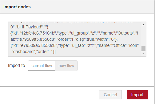
To import the Node-RED flow, go the Github repository or click the figure below to see the raw file, and copy the code provided.

Next, in the Node-RED window, at the top right corner, select the menu, and go to Import > Clipboard.

Then, paste the code provided and click Import.
Here’s the Node-RED flow you should get:

You have four different buttons to control the four different outputs. Each button is subscribed to a specific topic in which the ESP8266 #1 pusblishes messages to change the buttons’ state on Node-RED.
Each Node-RED button publishes on a topic that the ESP8266 #1 and ESP8266 #2 are subscribed to, so that they know when to change the outputs state.
Node-RED Dashboard
All widgets are grouped inside the Outputs group within the Office tab.

Accessing your Node-RED Using Interface
Go to http://Your_RPi_IP_address:1880/UI, and you should see the Node-RED user interface.

3D Printed Enclosure
To give this project a finished look, I’ve 3D printed an enclosure for the 3.2” Nextion display.

The enclosure has enough space to fit the display, the ESP8266 and the 433MHz transmitter.

You can download the .STL file for the Nextion housing for 3.5 inch. Note that for this project, I’ve used the Nextion 3.2”, so you need to resize those files to fit the Nextion 3.2” display.
The enclosure was printed using the Creality 3D CR–10 3D Printer – you can read my full review here.
Demonstration
With everything ready, you should be able to control your outputs by tapping the buttons on the Nextion display.

When you tap a button on the Nextion display, the Node-RED Dashboard updates instantly.

Watch the video at the beginning of the page, to see this project in action.
Wrapping Up
We hope you’ve found this project useful. After learning the concepts in this project, you can customize it to control practically anything you like with Node-RED using the Nextion display interface.
If you like this project, you’ll certainly like:
- Node-RED with WS2812B Addressable RGB LED Strip
- Build a Home Automation System with Node-RED
- Node-RED with Raspberry Pi Camera (Take Photos)
Thanks for reading.


Another great tutorial – keep up the good tutorials – they are some of the best, learn something each time…
Awesome! I plan to make this, thank you!
read
You can download the .STL file for the Nextion housing for 3.5 inch. Note that for this project, I’ve used the Nextion 3.2”, so you need to resize those files to fit the Nextion 3.2” display. What software do you use to resize?
Great tutorial! I found it while looking for a housing for a Nextion 3.2″ display. Unfortunately I have NO plan how to resize the .stl files for a 3.2″ display. So, can you share your resized files with us? That would be great.
No answer at all! Nobody at home?
Hi Rui
Have you considered doing a project where the Nextion combines buttons and displays (text, gauges, page changes, etc) that receive information from Node-RED.
What I’m thinking is a wall panel which would display current temperature, humidity, weather forecast or whatever (to be determined by Node-RED, based on time of day), has a single button over the top three quarters of the display for room light on/off and a row of smaller buttons at the bottom for calling other display functions.
Perche’ nel code 1 in questa riga
mySwitch.setPulseLength(REPLACE_WITH_YOUR_PULSE_LENGTH);
mi da’ l’errore REPLACE_WITH_YOUR_PULSE_LENGTH was not declared in this scope. Vi ho gia’ scritto alcuni giorni fa,ma nessuna risposta.grazie
Hi Federico.
Next time, try to post your questions in English so that everyone can understand.
You need to follow this tutorial to get the pulse length of your sockets: https://randomnerdtutorials.com/decode-and-send-433-mhz-rf-signals-with-arduino/
REPLACE_WITH_YOUR_PULSE_LENGTH is a placeholder for the pulse length.
So, you just need to replace that with the pulse length you get from the decoding rf signals tutorial.
Regards,
Sara
Dear Sara, it works fine, thanks a lot for your continuos suggestions. domenico
Hi. How can we display list data on Nextion display? For instance, one esp sends 10 sequently data to second esp, and the nextion display connected to the second esp shows that data in a list box. Are there any component to represent a list for Nextion enchanced edition?
Hello Mina,
I think NOT, that you will get an answer from Rui or Sara. My comment leaved unanswered since Oct. 2021. I wish you good luck that there is another guy who can help you.
Best regards,
Hans
Boa noite.
Parabéns pelo artigo!
Como coloco no sketch do arduino login e senha para o Broker MQTT ?
Obrigado
Hi.
When you call client.connect(), pass as second and third arguments the username and password.
For example:
client.connect(“ESP1_Office”);
should be:
client.connect(“ESP1_Office”, “USERNAME”, “PASSWORD”);
I hope this helps.
Regards,
Sara