OTA (Over the Air) update is the process of loading a new firmware to ESP8266 module using WiFi connection rather than a serial communication. This type of functionality is extremely useful in case of no physical access to the ESP module.
Uploading a new sketch wirelessly from Arduino IDE is intended for the following typical scenarios:
- during firmware development – as a quicker alternative to uploading a new sketch over a serial
- for updating the firmware of multiple ESPs in your network
If you like the ESP and you want to do more projects you can read my eBook Home Automation using ESP8266.
Let’s get started!

Step #1 – Uploading BasicOTA.ino with serial communication
In order to upload firmware to your ESP8266 wirelessly, you have to upload the BasicOTA.ino sketch example first.
Having the latest Arduino IDE software installed from arduino.cc/en/Main/Software. Follow these next instructions:
1) Connect your ESP8266 to your computer with a USB cable:

2) Go to Tools to select your ESP board model. You also have to choose your ESP’s COM port

3) Open the BasicOTA.ino example: File > Examples > Arduino OTA > BasicOTA.ino or copy the following sketch to your Arduino IDE
/*********
  Rui Santos
  Complete project details at https://randomnerdtutorials.com
  Arduino IDE example: Examples > Arduino OTA > BasicOTA.ino
*********/

#include <ESP8266WiFi.h>
#include <ESP8266mDNS.h>
#include <WiFiUdp.h>
#include <ArduinoOTA.h>

// Replace with your network credentials
const char* ssid = "YOUR_SSID";
const char* password = "YOUR_PASSWORD";

void setup() {
  Serial.begin(115200);
  Serial.println("Booting");
  WiFi.mode(WIFI_STA);
  WiFi.begin(ssid, password);
  while (WiFi.waitForConnectResult() != WL_CONNECTED) {
    Serial.println("Connection Failed! Rebooting...");
    delay(5000);
    ESP.restart();
  }

  // Port defaults to 8266
  // ArduinoOTA.setPort(8266);

  // Hostname defaults to esp8266-[ChipID]
  // ArduinoOTA.setHostname("myesp8266");

  // No authentication by default
  // ArduinoOTA.setPassword((const char *)"123");

  ArduinoOTA.onStart([]() {
    Serial.println("Start");
  });
  ArduinoOTA.onEnd([]() {
    Serial.println("\nEnd");
  });
  ArduinoOTA.onProgress([](unsigned int progress, unsigned int total) {
    Serial.printf("Progress: %u%%\r", (progress / (total / 100)));
  });
  ArduinoOTA.onError([](ota_error_t error) {
    Serial.printf("Error[%u]: ", error);
    if (error == OTA_AUTH_ERROR) Serial.println("Auth Failed");
    else if (error == OTA_BEGIN_ERROR) Serial.println("Begin Failed");
    else if (error == OTA_CONNECT_ERROR) Serial.println("Connect Failed");
    else if (error == OTA_RECEIVE_ERROR) Serial.println("Receive Failed");
    else if (error == OTA_END_ERROR) Serial.println("End Failed");
  });
  ArduinoOTA.begin();
  Serial.println("Ready");
  Serial.print("IP address: ");
  Serial.println(WiFi.localIP());
}

void loop() {
  ArduinoOTA.handle();
}
Note: you have to change the sketch example with your SSID and password.
4) Press the “Upload” button in the Arduino IDE and wait for the “Done uploading” message

5) Open the Arduino IDE serial monitor at a baud rate of 115200. If you’ve entered the right network credentials you should see your ESP IP address after a few seconds:

Step #2 – Uploading a new sketch OTA (Over the Air)
Now your ESP8266 is ready to receive OTA firmware updates. You can unplug your ESP8266 from your computer and power it through any power source (for example a power bank). If your ESP8266 has a wireless connection to your router, you should be fine to upload new firmware.

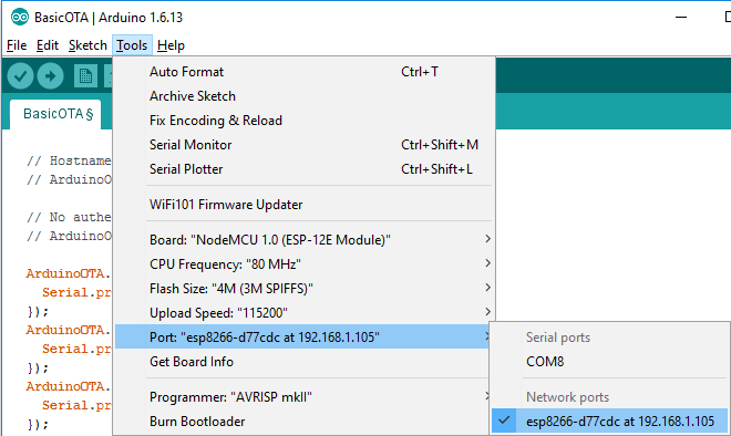
1) Go to your Arduino IDE. Open Tools tab select the Port option and you should see something like this: esp8266-xxxxxx at your_esp_ip_address
2) Copy the following sketch to your Arduino IDE and upload it to your ESP8266. This sketch blinks the ESP12-E NodeMCU kit built-in LED every second
/*********
  Rui Santos
  Complete project details at https://randomnerdtutorials.com
  Arduino IDE example: Examples > Arduino OTA > BasicOTA.ino
*********/

#include <ESP8266WiFi.h>
#include <ESP8266mDNS.h>
#include <WiFiUdp.h>
#include <ArduinoOTA.h>

// Replace with your network credentials
const char* ssid = "YOUR_SSID";
const char* password = "YOUR_PASSWORD";

const int ESP_BUILTIN_LED = 2;

void setup() {
  Serial.begin(115200);
  Serial.println("Booting");
  WiFi.mode(WIFI_STA);
  WiFi.begin(ssid, password);
  while (WiFi.waitForConnectResult() != WL_CONNECTED) {
    Serial.println("Connection Failed! Rebooting...");
    delay(5000);
    ESP.restart();
  }

  // Port defaults to 8266
  // ArduinoOTA.setPort(8266);

  // Hostname defaults to esp8266-[ChipID]
  // ArduinoOTA.setHostname("myesp8266");

  // No authentication by default
  // ArduinoOTA.setPassword((const char *)"123");

  ArduinoOTA.onStart([]() {
    Serial.println("Start");
  });
  ArduinoOTA.onEnd([]() {
    Serial.println("\nEnd");
  });
  ArduinoOTA.onProgress([](unsigned int progress, unsigned int total) {
    Serial.printf("Progress: %u%%\r", (progress / (total / 100)));
  });
  ArduinoOTA.onError([](ota_error_t error) {
    Serial.printf("Error[%u]: ", error);
    if (error == OTA_AUTH_ERROR) Serial.println("Auth Failed");
    else if (error == OTA_BEGIN_ERROR) Serial.println("Begin Failed");
    else if (error == OTA_CONNECT_ERROR) Serial.println("Connect Failed");
    else if (error == OTA_RECEIVE_ERROR) Serial.println("Receive Failed");
    else if (error == OTA_END_ERROR) Serial.println("End Failed");
  });
  ArduinoOTA.begin();
  Serial.println("Ready");
  Serial.print("IP address: ");
  Serial.println(WiFi.localIP());
  pinMode(ESP_BUILTIN_LED, OUTPUT);
}

void loop() {
  ArduinoOTA.handle();
  digitalWrite(ESP_BUILTIN_LED, LOW);
  delay(1000);
  digitalWrite(ESP_BUILTIN_LED, HIGH);
  delay(1000);
}
Note: you have to change the sketch example with your SSID and password.
3) Press the “Upload” button in the Arduino IDE and wait for the “Done uploading” message
4) Your ESP should have it’s built-in LED blinking every second
Wrapping Up
I hope this tutorial was useful. Now, you can have your ESP8266 in a remote location and update its firmware without having physical access to the ESP device.
Do you have any questions? Leave a comment down below.
Thanks for reading. If you like this post probably you might like my next ones, so please support me by subscribing my blog and my Facebook Page.


I definitely have to try this!
Thanks for sharing!
Make sure your ESP has 4 meg memory. The ESP-1 does not unless your change the memory chip yourself.
Any idea how to change the memory chip and what type?
There are some youtube videos that show how to do it. For example: youtube.com/watch?v=7Q6ABad7U6o
I have done it once and it was not too complicated.
The ESP-01 with 1Mb of flash works just fine with ArduinoOTA. OTA requires about 470Kb.
interesante articulo y muy necesario cuando trabajamos on dispositivos in-alambricos
Thanks for reading Luis!
Hi, Thank you for such a nice tutorial. This looks good if both the ArduinoIDE machine and the esp are within the same LAN (say home wi-fi). If my esp resides at a distant place under a different network, what changes need to be incorporated in the above steps and where, please? Thanks in advance.- Anupam
There’s not a good way of accomplishing that at the moment that I’m aware off
One solution to this is to use a hotspot wifi connection on your phone. Then you can bring your laptop and your phone with you to the remote location.
Normally, you use a hotspot to access the internet through your carrier but I think this should still work even where there is no coverage for your carrier.
Or you could programme an ESP to act as a hotspot…
I would try to have a secure vpn solution in place at that location..
I wonder why it is requird to install Phyton.
How/where is that being used?
To be honest I couldn’t find any Python file that is running during over the updates, but according to the official documentation it’s required Python 2.7 to run the OTA updates.
It is definitely running Python because on my system, the upload fails because it can’t find the executable! I posted earlier about this problem and am waiting for a reply.
esptool.py
I haven’t got Python installed on my Mac and this tutorial worked first time.
Thanks for a great addition to ESP8266. I have been wondering how to do OTA change for a long time. It will be useful for my auto lawn sprinkling system that uses a NodeMCU.
You’re welcome John, please note that this method only works with the Arduino IDE…
Thank you very much for this simple and neat explanation.
You’re welcome Keshav!
Thanks for reading,
Rui
Hi Rui, in the second sketch, ESP_BUILTIN_LED variable is defined inside setup and is not known in loop.
It must be declared as a global variable before setup
After that, the led blinks !
Alain
Fixed!
Thanks for letting me know Alain!
Asking for a password to download. What would it be?
Russ
The password is commented, so it shouldn’t ask for one. But try “123” without the quotes…
Unfortunaly the password does not work, any suggestion??
I am having the same password problem. The password line ” // ArduinoOTA.setPassword((const char *)”123″);” is commented out, but when I try to open the serial monitor it still prompts for a password. If I type 123 it still says wrong password. I even tried UNcommenting the password line and set it to “abc” to see if I could force it but when I type abc in the password field it still doesn’t accept it. I tried restarting the IDE and still no luck. Anyone have any thoughts?
On compiling the first script, I got an error regarding the ESP_BUILTIN_LED, so I moved its definition to the line before the setup() module.
The Arduino IDE now sees the new device on the IP address assigned. I selected the new device but when I attempt to load second script via OTA, it fails:
Sketch uses 238533 bytes (22%) of program storage space. Maximum is 1044464 bytes.
Global variables use 32881 bytes (40%) of dynamic memory, leaving 49039 bytes for local variables. Maximum is 81920 bytes.
12:18:37 [ERROR]: No response from device
12:18:37 [ERROR]: No response from device
Using Arduino 1.8.0 Hourly Build 2016/12/21 04:34 (Windows) for loading the first script.
Using the same and Arduino 1.8.0 Hourly Build 2016/12/29 04:25 (Linux) to attempt the OTA load.
I had a variable misplaced, but it should be fixed now.
Can you try to copy and paste the sketch again?
Thanks,
Rui
Could you explain this type of instruction ? I am lost…
ArduinoOTA.onProgress([](unsigned int progress, unsigned int total) {
Serial.printf(“Progress: %u%%\r”, (progress / (total / 100)));
});
Thanks,
Alain
It’s simply a nice way of printing the progress while uploading a new sketch for user visual feedback.
Thanks,
Rui
Thanks Rui, I understand what it does, it is similar to a software interrupt or callback, but I am lost with the syntax : what is the role of [ ] at the beginning ? maybe to put inside a function name (here, function is anonymous)
Alain
FYI, that appears to be a C++ lambda (aka anonymous function).
Hi Rui,
I have made your sketch and it is blinking at the end, however if i open the serial monitor it is asking “type board password to access its console” how about that, i tried differend passwords but with no effect.
Does something goes wrong or do i something wrong.
Regards Ton.
Excellent tutorial, Rui.
There was one problem on my system. The definition of a constant was not found as valid when the compiler was in the loop portion of the sketch. I had to add this inside the loop in the sketch: const int ESP_BUILTIN_LED = 2;
That worked. This is a nice capability.
When I tried to access the serial monitor when the blink program was running, it asked me for a password to access the board. I tried the WiFi password, but that didn’t work. Can you read the board’s serial port when it is running on WiFi?
Hi Stew,
I’ve fixed that variable error. Thanks for letting me know.
Just tried using OTA to upload a Weather Station sketch to an ESP-12.
The process appeared to work – the sketch compiled and wirelessly uploaded and started to run. But it fails to establish the WiFi connection it needs to download weather data. The sketch worked when loaded directly via USB. I presume there is a conflict with the WiFi that is used to transfer the program. Any hints on how to solve this?
I’m not sure… I’ve never encountered that issue, but as you said sounds like it’s not compatible with your program…
Stew, did you ever solve your issue? I seem to have a similiar issue. My sketch monitors sensors and initiates a http session to a server to upload the data. When i add the OTA code to the working sketch, it no longer is able to connect to the server to update sensor data. (connection fails). ArduinoOTA definitely conflicts with ESP8266HTTPClient code.
Hi Robert –
Sorry, I abandoned that project a ling time ago. I do hope you can get it working somehow.
Good luck.
I enjoy your tutorials, they are great (I even bought a couple of your books).
This time however, I get stuck here::
1) Go to your Arduino IDE. Open Tools tab select the Port option and you should see something like this: esp8266-xxxxxx at your_esp_ip_address
I get the IP address through the serial monitor but I can’t see the esp8266–xxxxxx at 192.168.1.x port after uploading the sketch in the Arduino IDE (version 1.6.13).
I tried two different computers, 3 different ESP, two different IDE versions all with the same results.
I can run Python 2.7 from Windows 10 through the run command so the path is installed correctly as well.
I Googled this procedure and it’s not any different from your tutorial, I’m at a loss, it’s as if I am missing a step somewhere…
Hi,
I hope you are doing well!
I think you might either need to restart your Arduino IDE or check if you have your firewall enabled. That might be blocking the connection…
Thank you for supporting my work,
Rui
I couldn’t get it to work without installing “Bonjour” – Windows doesn’t have this by default (although you may have installed it with something else historically).
If you are using the wifi part of the ESP (ie. More than just blinking a light) do you have to set up a switch (MQTT/Nodered) to choose updating and running. I saw this somewhere else. This feature would be a great add-on to you Home Automation book ( which I loved).
Thanks Chris for the feedback and suggestion. I need to research that, because that would be really handy to everyone.
Have a great day,
Rui
This sentence: “If your ESP8266 as a wireless connection to your router, you should be fine to upload new firmware.” doesn’t make sense as written. Is there a typo? Maybe it should say “If your ESP8266 HAS a wireless connection to your router…”? But even then, what does that mean? Does the OTA program take care of creating a wireless connection to the router? And my application makes the 8266 into an AP. Once I power up after loading my app, will I still be able to update the app over the air?
It was a typo. I’ve fixed it and thanks for letting me know.
The ESP needs to be in the same network of your computer, otherwise you will not find the ESP in the Arduino IDE.
Yup, that’s the idea, if you always upload a sketch that is capable of being updated over the air.
It has to be a sketch with a similar structure as the section: “Step #3 – Uploading a new sketch OTA”
I think your answer there is unclear & I was going to ask a similar question.
If I understand correctly, after you set up the ESP for OTA, then the OTA update will overwrite the OTA setup, so if you want to continue to use OTA, then the new sketch must include the OTA protocols and stuff.
Or put another way, we’re probably best off starting with the basic OTA sketch and writing our code into it…
Hi Keith.
Yes, that’s exactly that.
Regards,
Sara
That explains a lot! I couldn’t understand why it seemed to work fine the first time, but after that I got the [ERROR} No Answer message when I tried to upload.
So I will now have to find a way to wrap the OTA code around my program!
Great great great thankd
You’re welcome!
Thanks for reading,
Rui
I followed your tutorial, but do not run IDE on Windows but on a MAC. I installed Python 2.7.13 for MAC.
However, I dont see the proper ESP wifi port. What is the role of Python in this tutorial? Do I miss something or is this project not meant /tested for MAC?
If you do a search with an IP scanner in your network, can you see your ESP8266 IP address? (Or with the Arduino IDE serial monitor)
To be honest I couldn’t find any Python file that is running during over the updates, but according to the official documentation it’s required Python 2.7 to run the OTA updates.
Note: If OTA port does not show up, exit Arduino IDE, open it again and check if port is there. If it does not help, check your firewall and router settings. OTA port is advertised using mDNS service.
Thank you very much for this simple
You’re welcome! Thanks for reading
Kinda unrelated, but what would you recommend?
A Wemos D1 mini or an Amica NodeMCU?
Both of them cost pretty much the same (ok the Wemos is about 50 cents cheaper, but whatever)
I prefer the Wemos D1 Mini.
Itsss Really a good job!
But I have a doubt can we program twice or thrice or as many time times through OTA???
Yes, you can upload unlimited number of times, but the core OTA code should be in all the sketches that you upload
I’ve had problems with this. It uploaded OK and showed in the Serial Monitor that it was connected, but there was subsequently no other option showing under ports only the com port in use.
Also, if I close and reopen the Serial Monitor there’s no response. It’s the same if I hit the reset on the Node MCU – nothing.
It appears to be connected to the router as I’. seeing 5c:cf:7f:11:89:05 on IP address 137…
Any ideas?
how do I add OTA to an existing sketch that doesn’t have it to upload to a sonoff/esp8266? I have an Sonoff/esp8266 that has a sketch on it that has OTA. But I need to change it to a new one. The problem is the new one doesn’t have OTA in the code. How do I add it? I’m totally new to all this as you can probably tell. Thanks!
The Sonoff has very little memory, it’s very likely that will not be able to handle the OTA option.
You might consider upgrade the Sonoff memory…
Seems like a lot of people are running into password issues when trying to open the serial monitor over the air. Anyone have any ideas? I’m on a Mac, running the prerequisite Python and still get a password error every time I try to open the serial monitor. I tried all the obvious passwords, made sure the password line in the sample code is commented out. HELP IS GREATLY APPRECIATED.
As I wasn’t sure whiich of the files Rui had edited (bug fixed), I downloaded and reinstalled the Basic OTA sketch – no problems, it’s connected to the router and the serial monitor works. As before.
I then downloaded and reinstalled the OTA Blink sketch – no blinking LED and the serial monitor is still demanding a password…
I think there’s still a problem here Rui…!!!
NodeMCU board is an ESP12 type, not a 12E – not sure if that makes any difference.
My previous post may have been slightly misleading. The OTA Blink sketch doesn’t get to ‘Done uploading’.
I tried uncommenting the password line, other password, entering with and without “”, eveeything I could think of – then I found two things that may be relevant to this problem, but they’re a bit beyond me…
github.com/esp8266/Arduino/issues/965
github.com/esp8266/Arduino/blob/master/doc/ota_updates/readme.md#password-protection
Rui, can you work out a solution from those and explain it in an undestandable manner?
Thanks
Thanks for the detailed links and I hope that solves other readers problems, but since I didn’t encounter that issue I’m not able to know the answer for sure Duncan
If anyone finds a solution to this password problem, please, please post it…
I get as far as step 3-3 Press the Upload button … and I get the following error:
java.io.IOException: Cannot run program “python.exe”: CreateProcess error=2, The system cannot find the file specified
But I have python installed and it is in the path. For example, I can open a CMD window and type python, and it runs. I haven’t modified either of the two sketches other than changing the SSID and password on each of them. Any ideas?
I fixed the Python not found problem. I had to uninstall all previous Python installs. I should have looked at the Path variable before I did this to see what it had in it, maybe a reference to one of the earlier installs. But now it all works – at least with your test app. Now to try it with my own app. This will be great if it work with my app because all my ESP8266’s are inside enclosures and I don’t want to have to open them up every time I update the app.
Fantastic, Rui! I was afraid that I would have problems because my app makes the 8266 an Access Point with no password, while my network connection is a hotspot running on my phone and it has a different SSID and also a password. But DAMN, it all works. I am making and selling ESP8266-powered devices and the 8266’s are in enclosures . I frequently need to update the software, so being able to do this without taking the enclosure apart and hooking up a USB cable is a really nice thing for me. Thanks for the tutorial!
I am having problems now. I run into two different problems. Sometimes the Port list on the Arduino IDE shows a network port and sometimes it only shows COM ports. When it doesn’t, of course I can’t do OTA update. And I can’t figure out how to force the network port to appear in the list.
So that is problem 1. Why doesn’t the network port appear in the list and how can I force it to? When the network port does appear, the IP address that is part of the port address is always the same: 192.168.43.64. But the IP address that is displayed in the Serial Monitor when I upload the OTA loader often varies. And when the IP in the Port addres does not correspond with the IP displayed in the Serial Monitor, the update fails. But if the IP addresses match, then the update works fine. So I am assuming that the OTA loader saves the IP address it finds and expects the 8266 to always be at that address, which it is not. I don’t know how to get around this one either.
I should note that since I don’t have a router, I use a hotspot on my phone. I have double checked the SSID and password of the hotspot with those in the OTA loader and they are the same. I guess that is obvious from the fact that it sometimes works.
Any thoughts?
If you Can’t see IP address under the port lists (same to me) i advice to search and find ESPOTA.PY file directly, parametering in a .bat file, and run directly from CMD. its 100% works!
“If you Can’t see IP address under the port lists (same to me) i advice to search and find ESPOTA.PY file directly, parametering in a .bat file, and run directly from CMD. its 100% works!”
I have no idea what that means. Could you perhaps provide an example?
I am double posting these questions here and on the FB site to get a wider exposure in hopes that I can get this problem solved soon. The problem is that the Arduino IDE does not find and display the network port for the ESP. But from running an IP scanner, I can verify that the port exists and is live. The odd thing is that maybe once in twenty times that I open an instance of the IDE, the port shows up. The rest of the time it does not. Any ideas on this? I posted this problem to the Arduino forum also.
I found the solution! I did not find the root problem but I found the solution. Restarting the Bonjour Service is the solution. I do not know why that works but it does. On my Windows 10 machine the Bonjour Service was Running but I restarted it anyway and voila! The ESP appears in the port list! Just thought you would like to know!
Too soon! It turns out that restarting the Bonjour Service only worked once –
ust like other tries at a solution that I thought were the answer! What the hell is going on with this thing?
I have a similar problem (I don’t find it even once in 20 times 😛 ) However, if I remove blink code in loop, OTA can be found without any problem. For some reason, adding blink code (4 lines) causes the port not to be found.
It is working for me. I changed following line:
const int ESP_BUILTIN_LED = 2;
to
const int ESP_BUILTIN_LED = 1;
Since in ESP-01 module LED is connected to GPIO1.
WARNING: THIS WILL DISABLE SERIAL COMMUNICATION WITH ESP. Since GPIO1 is also used as serial line. However, programing with serial port (along with OTA) will still work as putting ESP in program mode will not run sketch & hence GPIO1 becomes free.
help me pleas I can not see my ESP8266 in ports section .
Hi.
That means you don’t have the drivers installed in your computer.
Search for the drivers and install it on your operating system.
Arrygon, you’ll see ESP8266 in ports only after you have downloaded the OTA sketch once. First time you need to download this sketch using serial port. Once done, restart your Arduino GUI & you should see ESP8266 in ports. However, before downloading first time using serial, you need to make sure to install the board support package for ESP in Arduino
I couldnt it to the board.It is always rebooting.It will be great if you solve this.
I’m not sure why that’s happening. It keeps rebooting after doing what? Make sure you are using a reliable power supply to power your ESP8266 board. Thanks for asking,
Rui
Do you have to maintain the OTA code in every sketch you up
load?
Hi Rick.
Yes, if you want to be able to upload code over the air in the future, you need to include OTA code in all your sketches.
Regards,
Sara 🙂
I had a problem but I found a solution, however crude. I’m posting this in case other users have a similar problem.
There was an error message when I tried to upload code to esp8266-xxxxxx. The loader espota.py was not found at location …/2.5.0-beta3/espota.py
The solution: click on Tools -> Board: -> Boards manager. Search for 8266 in upper right search box. One of the choices is esp8266 by ESP8266 community. The version that was already installed was 2.5.0-beta3. I clicked on the Select Version box and selected version 2.5.0-beta2 and updated it. Then it loaded.
Thanks for a really great tutorial.
Thanks for sharing the solution to your problem.
It may be useful for others.
Thank you so much.
Regards,
Sara 🙂
the loader uses a program called espota.py to load over the air instead of the usual loader esptool.py
Do you have a tutorial (or a tweak to this tutorial) that addresses configuring the WeMos “ATmega2560 ESP8266 CH340G” board for OTA? In particular, when to use the USB ESP8266 (firmware) switch settings vs. the USB ESP8266 (work) switch settings.
Or, does ArduinoOTA even work with the WeMos board?
The WeMos board is available here: banggood.com/Wemos-Mega-WiFi-R3-ATmega2560ESP8266-32Mb-Memory-USB-TTL-CH340G-Compatible-For-Arduino-Mega-p-1205437.html?cur_warehouse=CN
The identical RobotDyn board is available here: robotdyn.com/mega-wifi-r3-atmega2560-esp8266-flash-32mb-usb-ttl-ch340g-micro-usb.html
Hi Ron.
I don’t have any tutorial about what you’re looking for. Also, I’m not familiar with those boards.
I’m sorry that I can’t help much.
If anyone here knows something about this topic, please share.
Regards,
Sara
hi
thank you for your sharing
does it possible to do with gsm modem for example upload code on sim800l or sim808 with atmega328p?
Best Regards
Yes, it’s possible, but I don’t have any tutorials on that exact subject at the moment.
did u do it ?
if yes ? i have some questions about it?
I had a novel problem that might help others. The OTA BLINK sketch always worked: the network port showed up, and I was able to reflash. The same exact code in my program (in the same places) almost never showed the network port. Background: after setup() I run a 5 minute routine and then go into a lower-power mode (not Deep-sleep) for 30 minutes, and then the main loop starts again with turning the WiFi on since it just came out of low-power mode. Once I moved all of the OTA initialization AFTER that WiFi re-enable in loop(), everything worked. I tried simply moving the ArduinoOTA.begin() and ArduinoOTA.handle() after the WiFi re-enable, but that wasn’t enough. I guess you need to run the entire OTA initialization any time the WiFi has been re-enabled or re-configured. Of course the OTA can’t run with the WiFi in WiFi.forceSleepBegin(), but that’s OK. I can always power cycle it or hit it with RST to restart the 5 minute routine if I don’t want to wait for the loop to restart.
Could not get this to compile….Arduino couldn’t find the libraries?
Oi Rui, até aqui dá para entender mas…
Digamos que queremos carregar um sketch via OTA mas, que não esteja na mesma rede, ou seja, uma outra rede (roteador) que esteja longe da nossa casa; como proceder? Obrigado
Brilliantly useful tutorial – thanks for sharing this (grabbing your ebook as I speak!) – this will save me tonnes of manual running back and forth with temperature loggers I’ve built around the house!
Quick questions just to help my understanding:
1) I’ve uploaded the OTA script, then I’ve uploaded my own arduino code (temperature logger) – does this not wipe out the OTA, meaning if I wanted to update again I’d need to follow the same process? (I know it doesn’t seem to by your description, I just don’t know how it doesn’t!)
2) Is there any easy way to change the name of the ESP in the COM port? Am just thinking I’ve got 7-8 temperature loggers around the house and I’ll very quickly get confused! No problem if not, can obviously just write them down!
Hmm – spoke to soon!
Have uploaded OTA script to device fine, then connected via OTA to upload a script remotely, but get ’16:49:06 [ERROR]: No Answer’ on attempting to upload? Any ideas on this? Can share code if helps!
Hi.
When uploading a new sketch via OTA, it needs to include the code for OTA capabilities.
Otherwise, after uploading the new code, the ESP8266 won’t have OTA capabilities anymore and you won’t be able to upload new code over the air.
Regards,
Sara
This is cool. You might mention, most users will have to allow python script thru the firewall.
Josef MVP
I had “[ERROR]: No Answer” and did this:
Firewall and network protection-> Allow an app through firewall -> Change settings
Tick the 3 marks available (allow, private and public)
Thank you – this worked for me
Rui,
Is there anything you don’t know about ESP8266?
Just joking, your experience is invaluable to us novices.
Thanks,
John
Thanks John! I’m glad you find our work helpful.
Regards,
Rui
Rui:
I had trouble connecting until I listed the ESP8266’s ip address in my firewall’s “My Network Connections” to allow it to connect to my device. You can temporarily disable the firewall to see if it starts uploading but be certain to enable it as soon as you finish the test,
I hope this helps someone else having problems.
Dave
Nice tutorial on basic OTA functions. Thanks to the author for taking the time to put this together. It is very much appreciated.
Getting the OTA example to work on it’s own I found straight forward if the current sketch did not use a WEB server or WiFi.
Then I tried adding the OTA functions to a sketch that already had a WEB server and WiFi functions. I expect many ESP8266 applications already have WiFi and a WEB server as part of the application.
In my case I got stuck as adding the OTA functions disabled the present sketch’s WEB page server functions.
Just have not been able to integrate a sketch’s WEB page server with the OTA server.
I would really like to see a example(s) of how to add OTA to sketches that main function is already a WiFi based WEB page server.
I have this problem too!
If you find any solution on the WEB for this let me by posting it here as I have not found any references on integrating OTA and a WEB server.
Odd as a WEB server is what I expect what most ESP8266 are used for
how about this?
otadrive.com/
you can monitor and upgrade your esp8266 more easy.
Hi Sara and Rui,
just tested OTA with my existing codes/sketches on my ESP8266s. Workes perfectly!
To add the OTA part into the existing codes/sketches is not too much an issue, just makes it longer. Fine for me.
Also tested, if the SPIFFS (for the html, css, txt, etc.) files are also uploaded via OTA. Works perfectly , but as suspected: Only once.
Is there also a solution for the SPIFFS to upload always?
Don’t get me wrong. For me you are fabulous. Without you I would have spend weeks in the www/google/etc. to find what I need. Your website is just like a bible for me.
Konrad
Hi.
Thanks for sharing your experience.
Unfortunately, I’m not familiar with uploading files to SPIFFS via OTA.
I’ll have to take a look at that subject.
Meanwhile, if you find something, please share.
Regards,
Sara
Thanks Sara. For everything.
Small comment for all here getting this:— [ERROR]: No Answer’ —
This error message; – I got this too; – even after integrating the OTA part into the sketches.
It seems for me, that in some cases; – if I close the Arduino IDE completly (after saving the sketch) and re-opening the same sketch: – suddenly it worked. Perhaps this is coincidence, but I though I should participate this experience for others.
Konrad
Thanks for sharing.
Regards,
Sara
Hi Sara,
Subject: uploading into SPIFFS via OTA
Please accept, that I have to appologice for my incompetence.
If the sketch is correctly implemented with the neccessary AND correct OTA data; – AND the port to the CORRECT IP of the ESP8266 is clicked on; –> it works fine.
I have tried this now several times.
Both tools (SPIFFS together with OTA) are realy fantastic tools. 3 of my 4 ESP8266 are already working in this way perfectly. The 4th ESP will be changed also soon (as time allows it).
Unfortunatedly I have also an ESP32 (for email sending perposes). So I have to check the same thing now also for this on in your other ESP32 tutorial. Hope that works in the same way.
Sorry again – and thanks a lot.
Konrad
Hi Konrad.
If you don’t mind, can you share how you use the two tools together?
You can send an email to our support: https://randomnerdtutorials.com/support/
Refer me in the email and it will be forwarded to me.
Or I will send you an email, and if you are interested, just answer me.
Thanks
Regards,
Sara
Dear Sara,
Reason by network issues, sometimes i can not upload the sketch via WiFi, simple it’s stops. I know if i use my mobile phone hotstop there is no problem, so definetily there is a wired network problem by routers. When uploading stops, esp8266 need to be restarted manually, as it makes a ‘freeze’, i’d like to ask whether possible to programming a kind of watchdog for OTA uploading, so when OTA uploading may interrupt, ESP may restart automatically by itself (of course with the last good sketch)
Thanks for your reply in advance,
Can I create a code with OTA (port = 8266) + Wifi-server (port = 80)? My application is wifi-server only, but I want to update the code for server and do changes remotely via OTA?
Dear Ruy and Sara,
I have written a small program for an ESP-01 or ESP12s, using OTA.
It is intended to operate as a bridge between the serial port and WiFi/UDP.
When I send data to the serial port, (from the Arduino IDE, via USB, at this point in time), they are well received, decoded and displayed, but exception(29) follows and a general
reset occurs. Otherwise everything else runs fine.
Thanks for any help on the subject!
JPM
Hi.
Without further information, it is very difficult to find out what might be wrong.
Take a look at this and see if it helps:https://stackoverflow.com/questions/34483956/esp8266-exception-29
Regards,
Sara
Thank you, Sara. It was in fact a simple coding error (I am a beginner!). Sorry.
Don’t worry.
I’m glad you find the mistake.
Regards,
Sara
Thanks for this. I was wanting to use it in a garden irrigation project which will ideally be mounted to a bit of wood next to a relay – would be really handy to be able to update remotely! However the project also runs a web server (on a different port), and this seems to be interfering (your example sketch runs fine by itself, but when incorporated into the project both the HTTP server and the update server break).
Any suggestions please?
Hi.
Have you tried OTA updates using this library instead: https://github.com/ayushsharma82/AsyncElegantOTA
We have a tutorial for that:
– https://randomnerdtutorials.com/esp8266-nodemcu-ota-over-the-air-arduino/
Regards,
Sara
Thanks – I did see that, but I’m not running an async server at the moment, so I figured it would also cause problems. I did try the ESP32 version and it looks lovely and completely failed to work :-/
For the time being I’ve just unmounted the board (turns out the shield I had made somehow manages to pull around a pin which doesn’t like being pulled around at boot time, so it needs to be disconnected at every update anyway).
Hi again.
I don’t think it will cause problems. But the best way to discover is to try it out.
Additionally, it is very easy to implement.
Try it, and then tell me if it works.
Regads,
Sara
Thanks – I gave it a go – it did take longer than I’d hoped to get it working because I converted my preexisting code to run on an asyncserver so everything could run from the same server, but in retrospect that might not have been necessary (I think the reason I couldn’t see the updateserver previously might not have been an interference issue so much as the fact that I hadn’t set up that port for external access!).
I had the same issue with this that I’d previously had with the ESP32 version, in that it told me the update had been successful but the code stayed the same. However I found that verifying the code first and then clicking the “export compiled binary” did seem to work (even though that command does reply that it is compiling the sketch, so I don’t know why verifying the code first should be required!)
Anyhow, it is working now thanks.
Great!
Thanks for the follow-up.
Regards,
Sara
I’ve just had cause to use it in its natural environment (in a locked box, containing a relay I prefer not to touch without turning off the mains power (which also turns off the ESP), connected to a board which stops it from booting once connected (despite my attempts to find a set of pins which didn’t!). The whole thing is in the middle of a somewhat spikey hedge.
So I am very happy to report that it appears to have worked flawlessly! Many thanks once again!
Hi,
Works nice, though on the 2nd upload….
Question, does it work also on Non-same subnet? For example in another country?
How do you combine this when using SleepMode() and WakeUpMode()?
Hi.
It must be on the same network.
Regards,
Sara
I get errors when I try to compile the BasicOTA file, whether yours, or the one in the example files. The error is D:\ArduinoSketch\libraries\ESP8266WiFi\src/include/UdpContext.h:414:13: error: ‘esp_yield’ was not declared in this scope
If I comment out the line in file shown, I then get MORE xxx.xxx not declared in this scope in other files. I’ve tried sketches from others with same result. I’m using a WemosD1 board (An esp8266 board in UNO footprint format). I have the correct board selected. In fact I can blink the LED using the example blink program for the esp8266, just can’t run this exp8266Wifi library.
Hi Sara and Rui,
Thanks to Sara I came to this site. For a moment I thought and hoped to have found a working OTA. In part it is. Like many people, I get the message: “22:36:24 [ERROR]: No response from device”. From everything I found on the web I came up with a special solution. The error line contained “C:\Users\Jan\AppData\Local\Arduino15\packages\esp8266\tools\python3\3.7.2-post1/python3 -I C:\Users\Jan\AppData\Local\Arduino15\packages\esp8266\hardware\esp8266\3.0.2/tools/espota.py -i 192.168.178.127 -p 8266 –auth= -f P:\Tmp\arduino_build_21512/BasicOTA_2.ino.bin”.
Python 2.7.12 is indicated at the top. That’s why I installed this version after the error message. But that made no difference. While puzzling I made the following working script:
C:\Tmp>type Send.cmd
@echo off
cls
if .%2 == . goto :Error1
C:\Python27\python C:\Users\Jan\AppData\Local\Arduino15\packages\esp8266\hardware\esp8266\3.0.2/tools/espota.py -r -i 192.168.178.%1 -f %Temp%\arduino_build_%2\BasicOTA_2.ino.bin -d -P 40000 -p 8266
goto :Ready
:Error1
echo Syntax: %0 IP[4] BuildNumber
:Ready
echo.
echo Toets ENTER.
pause > nul
C:\Tmp>Send 127 21512
Arduino EDI apparently uses the wrong version of python.
I can’t find any indication that this can be changed.
Brilliant. Worked like a CHARM. First time.
Could not have been easier.
10 minutes and 2 of those were spent looking for scissors to snip open the antistatic bag.
Now I’m cooking on gas.
Many, MANY thanks.
Spenser
I can get my ESP8266 to blink…so I know it works, but whenever I try one of the wifi sketches, I get this error: ESP8266WiFi\src/include/UdpContext.h:414:13: error: ‘esp_yield’ was not declared in this scope
It has to do with the ESP8266Wifi library…not sure what I should edit the library or not. I’ve done this before and it only led to more errors (other errors), so I’m weary.
I gave up on OTA using Bluetooth and convinced the best way is OTA using ESP8266.
Any help is appreciated.
When I use Arduino IDE and a USB cable, the update is done and then shows a hard reset.
When I do OTA, I get the Updating…………….
How do I know when it is done?
Does the Arduino restart?
I did try and open the Serial Monitor but got an error “Serial Monitor is not supported on Network ports…..”
Hi
Many thanks for this tuto.
#Step2/ 1/ : my_esp_IP_xxx does not appear in Tools/Port.
Any idea ?
Tks
I just updated 4 esp’s
Make sure you updated the ssid and password to your network
if connector successfully should see the following output on the serial port
Serial.println(“Ready”);
Serial.print(“IP address: “);
Serial.println(WiFi.localIP());
worked like a champ I have 4 esp8266 swapping cables is a pain once you hit over 65
The OTA code by it’s self works fine and OTA updates work well.
BUT if I take perfectly working WEB server code for a IOT device (Temperature sensor and remote light control application) the WEB server code no longer responds to a connected browser.
The WiFiClient client = server.available(); function with the OTA update code added to the sketch never returns TRUE when a browser connects. If I remove the OTA libraries and code the IOT WEB server WiFiClient client = server.available(); function will again return true and the browser receives the IOT data.
Puzzled over this for a few days and internet searches have not provide me with a clue as ti the issue.
Yes, This Is Very Nice,
I Want Another One,
How To I Program The Atmega Ic ( Atmega324pb ) Using The ESP8266 Over The Air Methode
I used the Basic OTA sketch from the Generic 8266 Module, but I’m not seeing a port under Tools. Also will this work with an ESP01S?
You upload it by going to sketch….export compiled binary then sketch….show sketch folder. Drag the file in here to the webpage you get when you go to yourserver/upload.
This is a very useful project! I would like to get this clarified: when I upload a sketch it normally erases whatever was there. Now, how does that work with the BasicOTA sketch, will it remain in the ESP and not be erased when I upload my normal sketch (the one that does the every day work), so that I can upload that one again and again over WiFi? And what happens with the OTA sketch if I upload any other sketch through a usb cable?
I should have read other comments above more carefully. You must combine the BasicOTA sketch with your “work sketch”. This is in fact what Rui Santos has done is his blink sketch. OK, after realising this, I went ahead and combined Rui’s Web Server, with 2 buttons, with the BasicOTA sketch. And it worked. I have a few remarks and questions, though:
* I had the Web Server modified to include static IP address. When I look in the IDE for the network port, there are 2 ports: the static one and another one which uses a different IP address, which is presumably DNS assigned. The latter does not work. Took me some time to discover this, as in the IDE the one already selected is not visible in the list, so I did nott realise there were 2.
* The BasicOTA sketch includes: WiFi.mode(WIFI_STA); in my understanding the Web Server is an Access Point, not a Station. Nevertheless I included this, and it all works, but maybe someone can clarify what the point is of setting the WiFi.Mode.
* When uploading with WiFi I very often get: Error: no response. It looks like this is just caused by the quality of the LAN connection, just keep on trying and in the end uploading works.
* I have a suggestion for Rui to more explicitly mention that you have to merge BasicOTA with you “work sketch” at the end of this otherwise excellent tutorial.
Good tutorial, thank you.
My ESP8266 project uses timer0 interrupts, but OTA is not working in this case. OTA works if I comment out timer interrupt code. I have tried adding ‘noInterrpts()’ to Arduino.onStart callback but that doesn’t work either.
What is the way to use OTA with a project that runs with timer0 interrupt? I know using timer0 is not ‘recommended’ while using WiFi but in my project it is working fine.
More info:
Changing the code to use timer1 instead of timer0, gives no change – OTA does not connect when using timer0/1 interrupt.
Putting:
noInterrupts();
timer1_detachInterrupt();
inside the OTA onStart callback has no effect.
The only way i can get OTA working is by putting a button on the project that runs code:
noInterrupts();
timer1_detachInterrupt();
Then OTA works
What am I doing wrong?
Shouldn’t OTA disable interrupts before uploading code?
The way to use ArduinoOTA along with timer interrupts is as follows, I hope this can help someone facing this issue.
// Disable timer1 ready for OTA firmware update
// You can also disable timer0.
void ICACHE_FLASH_ATTR hw_timer_disable(void)
{
/* Note: disableInterrupts and detachInterrupt do not work in ArduinoOTA onStart callback. Use this function instead to disable interrupts BEFORE OTA upload begins. */
ETS_FRC1_INTR_DISABLE();

TM1_EDGE_INT_DISABLE();

TIMER_REG_WRITE(FRC1_CTRL_ADDRESS, 0);
}
// OTA Callback, disable all PWM and stop all running timers
ArduinoOTA.onStart(
hw_timer_disable();
analogWrite(LIGHT_PIN, 0); // stop PWM
});
// Set timer1 as interrupt timer example code
timer1_isr_init();
timer1_attachInterrupt(onTimerISR);
timer1_enable(TIM_DIV16, TIM_EDGE, TIM_LOOP);
timer1_write(clockCyclesPerMicrosecond() / 16 * 50000); // 50000uS = 20Hz = 50mS
Ref: https://www.esp8266.com/viewtopic.php?p=34411
Hi Rui,
This is my first attempt at OTA ; I’ve wanted to try for some time. I’ve seen several methods on RNT as well as other places, but this seems to be the simplest to get started. I completed the first part fine, and the ip address was reported via serial monitor fine.
But when I try to upload the sketch, I get an error that says “no answer”. Pretty ambiguous I know but that’s all I have to go on. Any suggestions?
Update to above, I switched to the 2.0.3 IDE and the blink sketch uploads and runs. Interestingly though, the Output window in the IDE continuously keeps saying “Uploading” in a sub-window, and won’t go away even if you click on the “clear output” button.
I’m still struggling with this concept.
On my first attempt I uploadedthe OTA sketch fine, then uploaded the blink sketch. I DID NOT add the blink to the OTA (or vice versa) the ESP went into the blink operation fine. I left it running overnight and found it in a state where the led was on solidly, and would not communicate by either OTA or serial port. This begs the question:
Can you revert back to serial uploading, if so how?
On the second attempt, I uploaded the OTA fine again then uploaded the flash configuration sketch in examples to verify flash size. Again I didn’t add the OTA to the sketch (DUH); The flash information was reported via the serial monitor. After shutting everything down, when starting up again, I find the OTA address not listed in the “Ports” menu, the ESP is no longer reporting the flash information. and I can’t communicate with it either via OTA or serial.
This means I’ve essentually “bricked” 2 ESP’s. I know I must be doing it wrong, but clearly don’t understand. Any help in understanding would be greatly appreciated.
My goal in all this was to be able to change parameters on remotely placed ESP’s running mqtt and/or webserver functions can OTA and webservers co-exist?
Hi.
Every time you upload a new sketch via OTA, that newly uploaded sketch needs to include the lines of code for OTA. Otherwise, the new code won’t have OTA and you won’t be able to upload a new code to the board via OTA.
You’ll need to upload a new OTA code via serial to add the OTA feature to you board again.
I hope this is clear.
Regards,
Sara
The article fails to stress that the OTA instruction
ArduinoOTA.handle();
must be included in the loop() of all future sketches you load. You can load a new sketch without the OTA instruction – once – but after that you have to go back to a USB connection to do a future load. Your 2 ESP’s aren’t “bricked” – just load another sketch that includes the OTA instruction, leave the OTA instruction in ALL your future uploads, and you will be good to go.
Thanks for that. I got one to communicate again, The other won’t respond to the com port or ota (the one with the solid on led). Which BTW is not listed in the port menu without restarting the IDE. I’ve tried using IDE 1.8.19 and 2.0.3 with generic modules (just fyi)
Thanks Ron. So if I understand corectly, I can upload a sketch including “ArduinoOTA.handle();
” and it will continue to take updates? Or do I need to incorporate a sketch et all like the OTA example in the IDE examples.
A sketch that contains a loop like the following should be able to be updated OTA:
void loop() {
ArduinoOTA.handle();
// Anything else you want your sketch to do goes here
}
Thanks again Ron. I’ve played around with that successfully, If I might pester you a bit more,:
I have multiple ESP’s running MQTT sending temperature readings back to a Rpi, and several others simply acting as asynchronous servers reporting direct to any cell phone on the local network that can access it’s IP address. I’ve set those IP’s as static. My confusion is; If OTA sets an IP address for uploading, can a web server be there assigning a different IP? When that happens wouldn’t I loose ability to see the OTA requests? Thanks again for your great help.
I’m not sure that the OTA process sets the IP address. In any case, whatever the IP address ends up being, your ESP will advertise its address and that is the address to which you will be able to successfully upload your sketch.
Not working. I can ping the device but when I try to load the code to blink the led I get this.
. Variables and constants in RAM (global, static), used 28960 / 80192 bytes (36%)
║ SEGMENT BYTES DESCRIPTION
╠══ DATA 1504 initialized variables
╠══ RODATA 1320 constants
╚══ BSS 26136 zeroed variables
. Instruction RAM (IRAM_ATTR, ICACHE_RAM_ATTR), used 60824 / 65536 bytes (92%)
║ SEGMENT BYTES DESCRIPTION
╠══ ICACHE 32768 reserved space for flash instruction cache
╚══ IRAM 28056 code in IRAM
. Code in flash (default, ICACHE_FLASH_ATTR), used 284852 / 1048576 bytes (27%)
║ SEGMENT BYTES DESCRIPTION
╚══ IROM 284852 code in flash
13:16:06 [ERROR]: No Answer
Failed uploading: uploading error: exit status 1
I have OTA working well on project, but when I deploy a 2nd module with a different Hostname, it does not show up as a choice in the Arduino IDE. I can see the 2 modules with the MDNS browser, so I know they are there and on the network. Is there a limit to only one OTA module to be used at a time? Ideally the IDE would let me select from one of several differently named modules to communicate with. Thanks.
Hi,
I’ve got many ideas by reading randomnerdtutorials, thank you for that,
the newest one is OTA!
Till now three esp8266 are running with OTA.
The 4th one should be placed in another LAN, connected with mine overy VPN by two FritzBoxes:
192.168.11.xxx is mine, 192.168.22.xxx the other one
But the IP-address of esp in “22” (sent by ArduinoOTA.handle() ??) is not found by the IDE here in “11”.
Is this constellation really impossible or can I get it to work?
Thank you!
Best Regards
Hi muc,
As you could read in quite a number of the replies, your ESP’s should be in the same subnet, but….
when you are able to route all traffice from one Fritzbox to the other and back, it might work in my opinion
Regards, Ruud
Hi Rui & Sara, Turns out this is a great solution to change setpoints on one of my remote ESP’s. I’m using an ESP-07 (with the external antenna connector) because it’s in a metal shed. I’m monitoring temperature via an 18B20 sensor, and if it gets close to freezing, turn on a small ceramic heater to bring the temperature up to a cut off point. Since I wasn’t sure exactly where those points should be, OTA makes it easy to change them without removing the ESP and bringing it back to the workbench. The one querky thing I noticed is that when I update the ESP using the OTA port, I get an error that says:
espota.py: error: option -p: invalid integer value: ‘{upload.port.properties.port}’.
Since the uploads appear to go, I’m not sure what that error is indicating. Can you enlighten me? Thanks
Actually It seems it is NOT updating now, it did update while on the bench, but now that I have it back in place it isn’t. I am receiving data from it so I know I’m linked. Confused….
Many thanks for this tutorial. For me enough to get OTA up and running for the first time. I am going to implement this on a few setups I have in my house. My suggestion is to explain better where exact in the code you put your own initial, setup and loop code.
The OTA update is working for me, but the serial monitor does not work:
“No Monitor available for the port protocol network. Could not connect to 192.168.1.133 network port”.
The IP is correct and exist.
(Arduino IDE 2.3.4)
What can i do? Use putty, but how?
Did you manage to fix this … ? I’ve just encountered the same issue.
Hi Nick.
Yes i think I got it to work.
I used the library TelnetStream2.
There is a nice and easy example and I can get the serial data out by exchanging “Serial.print” with “TelnetStream2.print” in the code.
With putty i can Telnet to the IPadress of my ESP8266 and see the prints.
From AI:
Here are the common solutions:
Use an External Serial-to-USB Adapter (FTDI):
Connect the board’s TX/RX pins to an FTDI adapter (like a SparkFun FTDI Basic) and your computer, then use the standard Serial Monitor.
Implement Telnet/WebSockets for Wireless Debugging:
TelnetSerialStream: Use libraries like this one on GitHub or similar to redirect Serial.print() to a Telnet server on the device, viewable via a terminal like PuTTY.
ESP-IDF WebSockets: For ESP32, ESP-IDF offers built-in WebSocket support for remote logging.
Use the PlatformIO IDE:
PlatformIO’s serial monitor can often handle OTA devices better, allowing you to select the OTA port for monitoring, though it might still need specific configuration.
Use IP-Based Logging (Advanced):
Libraries (like TnetStream mentioned in) can redirect serial output over TCP/IP to a specific port, allowing you to monitor remotely without physical connection.