This tutorial is a getting-started guide for the DS3231 Real Time Clock Module with the ESP32. The DS3231 RTC module is a great module for accurate timekeeping, it also allows you to set alarms, output square waves with different frequencies, and get temperature readings.
Using a DS1307 RTC Module? Follow this tutorial instead: ESP32: Guide for DS1307 Real Time Clock Module (RTC).
Table of Contents
In this tutorial, we’ll cover the following topics:
- Introducing Real-Time Clock (RTC) Modules
- Introducing the DS3231 RTC Module
- Connecting the DS3231 RTC Module to the ESP32
- Installing the RTCLib Library
- ESP32 with DS3231: Setting and Reading the Time
- ESP32 with DS3231: Setting Alarms
Introducing Real-Time Clock (RTC) Modules
RTC modules, such as the DS3231 and DS1307, have their own tiny clock inside to keep track of time by themselves. Usually, they come with a battery holder to connect a battery so that they keep working even if the ESP32 resets or loses power.

The DS3231 and the DS1307 are some of the most popular choices to use with microcontrollers. Both are compatible with the ESP32 and communicate via I2C communication protocol. The DS3231 is more accurate because it gives temperature-compensated results. Additionally, it’s also possible to set external alarms with the DS3231, which can be extremely useful.
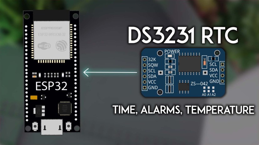
Introducing the DS3231 RTC Module
The following picture shows the DS3231 RTC Module. It uses a 32kHz temperature-compensated crystal oscillator (TCXO ) to keep track of time in a precise way (it’s resistant to temperature changes). Because of that, it also allows you to get temperature data.

Besides keeping track of the date and time precisely, it also has built-in memory for storing up to two alarms and can output square waves at different frequencies: 1Hz, 4kHz, 8kHz, and 32kHz.
You communicate with the RTC module using I2C communication protocol. Usually, it’s on address 0x68.
This module also comes with a 24C32 32-byte EEPROM that you can use to store any non-volatile data that you want. You can communicate with this EEPROM memory via I2C by addressing the right address (0x57).
DS3231 Battery Holder
The DS3231 comes with a battery holder to connect a battery to keep accurate timekeeping. In the event of a power outage, it can still keep track of time accurately and keep all the alarms.
You should use a LIR2032 battery, which is rechargeable. Don’t use a CR2032 (not rechargeable).


If you want to use a CR2032 battery, which is non-rechargeable, you must disconnect the battery charging circuit by unsoldering and removing the resistor (labelled R4 in my module) next to the diode.

DS3231 Alarms
The DS3231 can store up to two alarms: alarm 1 and alarm 2. These alarms can be configured to trigger based on a specific time and/or date. When an alarm is triggered, the SQW pin of the module outputs a LOW signal.
You can detect this signal with the ESP32 and trigger interrupts, or even to wake it up from deep sleep. Thus, this feature is extremely useful for setting a periodic deep sleep wake-up and other periodic tasks, time-based automation and also one-time alerts (because you can clear an alarm after it’s triggered).
Each alarm can be configured to be triggered in different modes. These modes allow you to create alarms that repeat every second, minute, hour, daily, weekly, or even once a month.
Alarm 1:
- Every second
- When seconds, minutes, hours, day or date match
Alarm 2:
- Every minute
- When minutes, hours, day or date match
We’ll see how to set alarms later in this tutorial.
DS3231 RTC Module I2C Address
By default, the address of the DS3231 RTC is 0x68 and the EEPROM connected to the module is 0x57. You can run an I2C scanner sketch to double-check the addresses.

DS3231 RTC Module Pinout
The following table quickly describes the DS3231 RTC Module Pinout.
| 32K | 32kHz oscillator output — can be used as a clock reference |
| SQW | Square wave/Interrupt output |
| SCL | SCL pin for I2C |
| SDA | SDA pin for I2C |
| VCC | Provides power to the module (3.3V or 5V) |
| GND | GND |
Connecting the DS3231 RTC Module to the ESP32
Here’s a list of the parts required for this tutorial:
You can use the preceding links or go directly to MakerAdvisor.com/tools to find all the parts for your projects at the best price!

Wire the DS3231 to the ESP32. You can use the following table as a reference or take a look at the schematic diagram.
| DS3231 RTC Module | ESP32 |
| SQW | GPIO 4 (or any other digital pin) |
| SCL | GPIO 22 |
| SDA | GPIO 21 |
| VCC | 3V3 |
| GND | GND |

You may also like: Guide for I2C Communication with the ESP32
Working with the RTC
Using an RTC module in your projects always requires two important steps.
- Setting the current time: you can do it manually by inserting the current time (or a different desired time) on the code; the system’s local time; or get the time from an NTP server.
- Retaining the time: to make sure the RTC keeps the correct time, even if it loses power, it needs to be connected to a battery. RTC modules come with a battery holder, usually for a coin cell.
Installing the RTCLib Library
We’ll program the ESP32 using Arduino IDE. Make sure you have the ESP32 boards installed by following this guide: Installing ESP32 Board in Arduino IDE 2 (Windows, Mac OS X, Linux)
There are several libraries to interface with the DS3231 RTC module. We’ll use the RTCLib from Adafruit that is compatible with DS1307, DS3231, and PCF8523 RTC modules. Additionally, this library is also compatible with ESP32 boards (even though that’s not mentioned on the library page).
In the Arduino IDE, go to Sketch > Include Library > Manage Libraries. Search for RTCLib and install the library by Adafruit. We’re using version 2.1.4.

ESP32 with DS3231: Setting and Reading the Time

The following example sets the time on the RTC clock, and then reads the time in the loop every three seconds. We also read the temperature. This code shows two different ways to set the time: synchronizing the RTC with the system time (date and time the sketch was compiled), and setting a specific date and time manually by writing it yourself on the code.
/*********
  Rui Santos & Sara Santos - Random Nerd Tutorials
  Complete instructions at https://RandomNerdTutorials.com/esp32-ds3231-real-time-clock-arduino/
*********/

// Based on the RTCLib Library examples: https://github.com/adafruit/RTClib
// Date and time functions using a DS1307 RTC connected via I2C and Wire lib
#include "RTClib.h"

RTC_DS3231 rtc;

char daysOfTheWeek[7][12] = {"Sunday", "Monday", "Tuesday", "Wednesday", "Thursday", "Friday", "Saturday"};

void setup () {
  Serial.begin(115200);

  if (! rtc.begin()) {
    Serial.println("Couldn't find RTC");
    Serial.flush();
    while (1) delay(10);
  }

  if (rtc.lostPower()) {
    Serial.println("RTC lost power, let's set the time!");
    // When time needs to be set on a new device, or after a power loss, the
    // following line sets the RTC to the date & time this sketch was compiled
    rtc.adjust(DateTime(F(__DATE__), F(__TIME__)));
    // This line sets the RTC with an explicit date & time, for example to set
    // January 21, 2014 at 3am you would call:
    //rtc.adjust(DateTime(2014, 1, 21, 3, 0, 0));
  }

  // When time needs to be re-set on a previously configured device, the
  // following line sets the RTC to the date & time this sketch was compiled
  //rtc.adjust(DateTime(F(__DATE__), F(__TIME__)));
  // This line sets the RTC with an explicit date & time, for example to set
  // January 21, 2014 at 3am you would call:
  //rtc.adjust(DateTime(2014, 1, 21, 3, 0, 0));
}

void loop () {
  // Get the current time from the RTC
  DateTime now = rtc.now();

  // Getting each time field in individual variables
  // And adding a leading zero when needed;
  String yearStr = String(now.year(), DEC);
  String monthStr = (now.month() < 10 ? "0" : "") + String(now.month(), DEC);
  String dayStr = (now.day() < 10 ? "0" : "") + String(now.day(), DEC);
  String hourStr = (now.hour() < 10 ? "0" : "") + String(now.hour(), DEC);
  String minuteStr = (now.minute() < 10 ? "0" : "") + String(now.minute(), DEC);
  String secondStr = (now.second() < 10 ? "0" : "") + String(now.second(), DEC);
  String dayOfWeek = daysOfTheWeek[now.dayOfTheWeek()];

  // Complete time string
  String formattedTime = dayOfWeek + ", " + yearStr + "-" + monthStr + "-" + dayStr + " " + hourStr + ":" + minuteStr + ":" + secondStr;

  // Print the complete formatted time
  Serial.println(formattedTime);

  // Getting temperature
  Serial.print(rtc.getTemperature());
  Serial.println("ºC");

  Serial.println();
  delay(3000);
}
How Does the Code Work
Start by importing the RTCLib library.
#include "RTClib.h"Then, create an RTC_DS3231 object called rtc.
RTC_DS3231 rtc;Then, you create a char array with the days of the week.
char daysOfTheWeek[7][12] = {"Sunday", "Monday", "Tuesday", "Wednesday", "Thursday", "Friday", "Saturday"};You can access each day by its index. For example:
- daysOfTheWeek[0] will return “Sunday”.
- daysOfTheWeek[1] will return “Monday”.
In the setup(), initialize the Serial Monitor.
Serial.begin(115200);Initialize the RTC module as follows:
if (! rtc.begin()) {
  Serial.println("Couldn't find RTC");
  Serial.flush();
  while (1) delay(10);
}
Checking the RTC Status
Then, check if the RTC has lost power with the lostPower() function. If it is not running, because it is a new device or because the battery backup failed, we’ll print a message in the Serial Monitor and set the time.
if (rtc.lostPower()) {
  Serial.println("RTC lost power, let's set the time!");
Setting the Time
To set the time on the RTC, we can use the adjust() method on our rtc object. The following line sets the RTC’s date and time to the current date and time when this sketch was last compiled.
rtc.adjust(DateTime(F(__DATE__), F(__TIME__)));__DATE__ and __TIME__ are macros that provide the current date and time at compilation.
Alternatively, you can set the date and time manually. Pass the time fields in this order: year, month, day, hour, minute, second. This line is commented on the code.
// January 21, 2014 at 3am you would call:
rtc.adjust(DateTime(2014, 1, 21, 3, 0, 0));
If you need to re-set the time on a previously configured device, you can call one of the previous two lines to set the time without checking if it has lost power or not (this is commented on the code).
// When time needs to be re-set on a previously configured device, the
// following line sets the RTC to the date & time this sketch was compiled
//rtc.adjust(DateTime(F(__DATE__), F(__TIME__)));
// This line sets the RTC with an explicit date & time, for example to set
// January 21, 2014 at 3am you would call:
//rtc.adjust(DateTime(2014, 1, 21, 3, 0, 0));
Getting Date and Time
In the loop(), we get the date and time every three seconds, and we print it in the Serial Monitor.
We call rtc.now() to get the current date and time from the RTC module.
DateTime now = rtc.now();It returns a DateTime object containing the values for the current year, month, day, hour, minute, and second.
To access each field of the date and time, we can use the following methods:
| now.year() | Gets the current year (e.g., 2024) |
| now.month() | Gets the current month (1–12) |
| now.day() | Gets the current day of the month (1–31) |
| now.dayOfTheWeek() | Gets the day of the week (0-6), where 0 is Sunday, and 6 is Saturday |
| now.hour() | Gets the current hour (0–23) |
| now.minute() | Gets the current minute (0–59) |
| now.second() | Gets the current second (0–59) |
To convert the result into a string, we can use the String() method. We also pass DEC as a second argument to the string() method to get a decimal number.
String yearStr = String(now.year(), DEC);In the case of the month, day, hour, minute, and second, we add a leading zero when the number is smaller than 10. So, instead of having, for example: 3:5:6 (which is weird for a time format), you’ll get 03:05:06.
String monthStr = (now.month() < 10 ? "0" : "") + String(now.month(), DEC);
String dayStr = (now.day() < 10 ? "0" : "") + String(now.day(), DEC);
String hourStr = (now.hour() < 10 ? "0" : "") + String(now.hour(), DEC);
String minuteStr = (now.minute() < 10 ? "0" : "") + String(now.minute(), DEC);
String secondStr = (now.second() < 10 ? "0" : "") + String(now.second(), DEC);
To get the name of the day of the week, we use the daysOfTheWeek array we created at the beginning of the code.
String dayOfWeek = daysOfTheWeek[now.dayOfTheWeek()];In the end, we concatenate all the time fields in a variable and display it in the Serial Monitor.
// Complete time string
String formattedTime = dayOfWeek + ", " + yearStr + "-" + monthStr + "-" + dayStr + " " + hourStr + ":" + minuteStr + ":" + secondStr;

// Print the complete formatted time
Serial.println(formattedTime);
The DS3231 gives temperature-compensated results. We can get the temperature it measures using the getTemperature() method on the rtc object. This returns the temperature in Celsius degrees.
 // Getting temperature
 Serial.print(rtc.getTemperature());
 Serial.println("ºC");
Testing the Example
With the RTC connected to the ESP32, upload the code to your board.
Open the Serial Monitor at a baud rate of 115200. The ESP32 will set the RTC time and display the current time and temperature every three seconds.

DS3231 with the ESP32: Setting Alarms

The DS3231 RTC Module allows you to set up to two alarms: alarm 1 and alarm 2. When using the RTCLib Library, these are the accepted modes for the alarms:
| Alarm | Mode | Meaning (Trigger the alarm…) |
| Alarm 1 | DS3231_A1_PerSecond | every second |
| Alarm 1 | DS3231_A1_Second | when the seconds match |
| Alarm 1 | DS3231_A1_Minute | when the minutes match |
| Alarm 1 | DS3231_A1_Hour | when the hour matches |
| Alarm 1 | DS3231_A1_Date | when the date matches |
| Alarm 1 | DS3231_A1_Day | when the day matches |
| Alarm 2 | DS3231_A2_PerMinute | every minute |
| Alarm 2 | DS3231_A2_Minute | when the minutes match |
| Alarm 2 | DS3231_A2_Hour | when the hour matches |
| Alarm 2 | DS3231_A2_Date | when the date matches |
| Alarm 2 | DS3231_A2_Day | when the day matches |
The following example shows how to set up two alarms and how to use them to trigger an interrupt on the ESP32 (learn more about interrupts with the ESP32 here).
/*********
  Rui Santos & Sara Santos - Random Nerd Tutorials
  Complete instructions at https://RandomNerdTutorials.com/esp32-ds3231-real-time-clock-arduino/
*********/

// Example based on the RTClib: implementation of an alarm using DS3231 https://github.com/adafruit/RTClib
#include <RTClib.h>
RTC_DS3231 rtc;

char daysOfTheWeek[7][12] = {"Sunday", "Monday", "Tuesday", "Wednesday", "Thursday", "Friday", "Saturday"};

// the pin that is connected to SQW
#define CLOCK_INTERRUPT_PIN 4

// LED for visual indication
const int ledPin = 2;

// set the alarms
// (year, month, day, hour, minutes, seconds)
DateTime alarm1Time = DateTime(2024, 12, 18, 12, 49, 0);
DateTime alarm2Time = DateTime(2024, 12, 18, 11, 10, 0);

void printCurrentTime(){
  // Get the current time from the RTC
  DateTime now = rtc.now();

  // Getting each time field in individual variables
  // And adding a leading zero when needed;
  String yearStr = String(now.year(), DEC);
  String monthStr = (now.month() < 10 ? "0" : "") + String(now.month(), DEC);
  String dayStr = (now.day() < 10 ? "0" : "") + String(now.day(), DEC);
  String hourStr = (now.hour() < 10 ? "0" : "") + String(now.hour(), DEC);
  String minuteStr = (now.minute() < 10 ? "0" : "") + String(now.minute(), DEC);
  String secondStr = (now.second() < 10 ? "0" : "") + String(now.second(), DEC);
  String dayOfWeek = daysOfTheWeek[now.dayOfTheWeek()];

  // Complete time string
  String formattedTime = dayOfWeek + ", " + yearStr + "-" + monthStr + "-" + dayStr + " " + hourStr + ":" + minuteStr + ":" + secondStr;

  // Print the complete formatted time
  Serial.println(formattedTime);
}

void onAlarm() {
  Serial.println("Alarm occurred!");
  // toggle the current LED state
  int state = digitalRead(ledPin);
  digitalWrite(ledPin, !state);
}

void setup() {
  Serial.begin(115200);
  pinMode (ledPin, OUTPUT);
  digitalWrite(ledPin, LOW);

  // initializing the rtc
  if(!rtc.begin()) {
    Serial.println("Couldn't find RTC!");
    Serial.flush();
    while (1) delay(10);
  }

  if(rtc.lostPower()) {
    // this will adjust to the date and time at compilation
    rtc.adjust(DateTime(F(__DATE__), F(__TIME__)));
  }
  // Uncomment if you need to adjust the time
  // rtc.adjust(DateTime(F(__DATE__), F(__TIME__)));

  //we don't need the 32K Pin, so disable it
  rtc.disable32K();

  // Trigger an interrupt when the alarm happens
  pinMode(CLOCK_INTERRUPT_PIN, INPUT_PULLUP);
  attachInterrupt(digitalPinToInterrupt(CLOCK_INTERRUPT_PIN), onAlarm, FALLING);

  // set alarm 1, 2 flag to false (so alarm 1, 2 didn't happen so far)
  // if not done, this easily leads to problems, as both register aren't reset on reboot/recompile
  rtc.clearAlarm(1);
  rtc.clearAlarm(2);

  // stop oscillating signals at SQW Pin, otherwise setAlarm1 will fail
  rtc.writeSqwPinMode(DS3231_OFF);

  // turn off alarm 2 (in case it isn't off already)
  // again, this isn't done at reboot, so a previously set alarm could easily go overlooked
  rtc.disableAlarm(2);

  // Schedule Alarm1 to fire when the minutes match
  if(!rtc.setAlarm1(alarm1Time, DS3231_A1_Minute)) {  // this mode triggers the alarm when the minutes match
    Serial.println("Error, alarm wasn't set!");
  }else {
    Serial.println("Alarm 1 will happen at specified time");
  }
}

void loop() {
  // print current date and time
  printCurrentTime();

  // Get Details about the alarm1
  DateTime alarm1 = rtc.getAlarm1();
  Ds3231Alarm1Mode alarm1mode = rtc.getAlarm1Mode();
  char alarm1Date[12] = "DD hh:mm:ss";
  alarm1.toString(alarm1Date);
  Serial.print("[Alarm1: ");
  Serial.print(alarm1Date);
  Serial.print(", Mode: ");
  switch (alarm1mode) {
    case DS3231_A1_PerSecond: Serial.print("PerSecond"); break;
    case DS3231_A1_Second: Serial.print("Second"); break;
    case DS3231_A1_Minute: Serial.print("Minute"); break;
    case DS3231_A1_Hour: Serial.print("Hour"); break;
    case DS3231_A1_Date: Serial.print("Date"); break;
    case DS3231_A1_Day: Serial.print("Day"); break;
  }
  // the value at SQW-Pin (because of pullup 1 means no alarm)
  Serial.print("] SQW: ");
  Serial.print(digitalRead(CLOCK_INTERRUPT_PIN));
  // whether a alarm fired
  Serial.print(" Fired: ");
  Serial.print(rtc.alarmFired(1));

  // Only one alarm can be set at a time, reset alarm 1 and activate alarm 2
  // resetting SQW and alarm 1 flag
  // the next alarm could now be configurated
  if (rtc.alarmFired(1)) {
      rtc.clearAlarm(1);
      Serial.println(" - Alarm cleared");

      // Set Alarm 2
      if(!rtc.setAlarm2(alarm2Time, DS3231_A2_Minute)) {  // this mode triggers the alarm when the minutes match
        Serial.println("Error, alarm wasn't set!");
      }else {
        Serial.println("Alarm 2 will happen at specified time");
      }

    // Get Details about the alarm2
    DateTime alarm1 = rtc.getAlarm2();
    Ds3231Alarm2Mode alarm2mode = rtc.getAlarm2Mode();
    char alarm2Date[12] = "DD hh:mm:ss";
    alarm1.toString(alarm2Date);
    Serial.print("[Alarm2: ");
    Serial.print(alarm2Date);
    Serial.print(", Mode: ");
    switch (alarm2mode) {
      case DS3231_A2_PerMinute: Serial.print("Every Minute"); break;
      case DS3231_A2_Minute: Serial.print("Minute"); break;
      case DS3231_A2_Hour: Serial.print("Hour"); break;
      case DS3231_A2_Date: Serial.print("Date"); break;
      case DS3231_A2_Day: Serial.print("Day"); break;
    }
    // the value at SQW-Pin (because of pullup 1 means no alarm)
    Serial.print("] SQW: ");
    Serial.print(digitalRead(CLOCK_INTERRUPT_PIN));
    // whether a alarm fired
    Serial.print(" Fired: ");
    Serial.print(rtc.alarmFired(1));
  }

  Serial.println();
  delay(2000);
}
Important notes about the alarms:
- the RTC allows you to save up to two alarms;
- you can only have one alarm active at a time;
- after an alarm is triggered, you must clear its flag to avoid triggering and crashing the ESP32;
- you must deactivate an alarm before activating the other.
How Does the Code Work?
We’ve already covered how to initialize the RTC, set and get the time from the DS3231 module. We’ll just explain the relevant parts related to the alarms.
Define the GPIO that is connected to the SQW pin. In our case, we’re using GPIO 4, you can use any other suitable GPIO.
// the pin that is connected to SQW
#define CLOCK_INTERRUPT_PIN 4
First, we create two DateTime objects to set the time for alarm 1 and alarm 2.
DateTime alarm1Time = DateTime(2024, 12, 18, 12, 05, 0);
DateTime alarm2Time = DateTime(2024, 12, 18, 11, 10, 0);
Then, we need to disable the 32k pin because we won’t use it.
rtc.disable32K();Set the SQW pin as an interrupt so that we can trigger a function when an alarm is fired. The SQW is active low, which means its state is normally HIGH and changes to LOW when an alarm is fired. When the alarm is triggered, we’ll call the onAlarm function.
// Trigger an interrupt when the alarm happens
pinMode(CLOCK_INTERRUPT_PIN, INPUT_PULLUP);
attachInterrupt(digitalPinToInterrupt(CLOCK_INTERRUPT_PIN), onAlarm, FALLING);
The onAlarm() function, defined previously in the code, prints a message in the Serial Monitor and inverts the current state of GPIO 2 (connected to the ESP32 onboard LED).
void onAlarm() {
  Serial.println("Alarm occured!");
  int state = digitalRead(ledPin);
  digitalWrite(ledPin, !state);
}
Clear both alarm 1 and alarm 2 before setting any alarm.
rtc.clearAlarm(1);
rtc.clearAlarm(2);
We’ll use the SQW pin to trigger the alarms. We won’t use its functionality to generate square waves. So, we need to stop that.
rtc.writeSqwPinMode(DS3231_OFF);We can only have one alarm going at a time. So, disable alarm 2 before setting up alarm 1.
rtc.disableAlarm(2);Set up the alarm 1 using the setAlarm1() function on the rtc object. Pass as arguments the time for alarm 1 and the alarm mode. We’ve already seen the alarm mode options for alarm 1 and alarm 2 before. In this case, we’re setting it to DS3231_A1_Minute, which means the alarm will fire when the minutes match.
// Schedule Alarm1 to fire when the minutes match
if(!rtc.setAlarm1(alarm1Time, DS3231_A1_Minute)) {  // this mode triggers the alarm when the minutes match
  Serial.println("Error, alarm wasn't set!");
}else {
  Serial.println("Alarm 1 will happen at specified time");
}
In the loop(), we print the details of the current alarm.
// Get Details about the alarm1
DateTime alarm1 = rtc.getAlarm1();
Ds3231Alarm1Mode alarm1mode = rtc.getAlarm1Mode();
char alarm1Date[12] = "DD hh:mm:ss";
alarm1.toString(alarm1Date);
Serial.print("[Alarm1: ");
Serial.print(alarm1Date);
Serial.print(", Mode: ");
switch (alarm1mode) {
  case DS3231_A1_PerSecond: Serial.print("PerSecond"); break;
  case DS3231_A1_Second: Serial.print("Second"); break;
  case DS3231_A1_Minute: Serial.print("Minute"); break;
  case DS3231_A1_Hour: Serial.print("Hour"); break;
  case DS3231_A1_Date: Serial.print("Date"); break;
  case DS3231_A1_Day: Serial.print("Day"); break;
}
// the value at SQW-Pin (because of pullup 1 means no alarm)
Serial.print("] SQW: ");
Serial.print(digitalRead(CLOCK_INTERRUPT_PIN));
// whether a alarm fired
Serial.print(" Fired: ");
Serial.print(rtc.alarmFired(1));
We can check whether alarm 1 has fired using the following line:
if (rtc.alarmFired(1)) {When it fires, we clear that alarm and start setting up alarm 2.
// Set Alarm 2
if(!rtc.setAlarm2(alarm2Time, DS3231_A2_Minute)) {  // this mode triggers the alarm when the minutes match
  Serial.println("Error, alarm wasn't set!");
}else {
  Serial.println("Alarm 2 will happen at specified time");
}
This is just a quick example showing you the details about setting up alarms with the DS3231 RTC module. Now, you should be able to modify this example to use alarms in your own projects. This alarm feature can be specially useful to wake-up the ESP32 from deep sleep at a designated time or to schedule periodic tasks that need to run at a specific time.
After uploading the code, you should get information on the Serial Monitor about the alarms. The ESP32 onboard LED will toggle every time an alarm is fired.

Wrapping Up
In this tutorial, you learned how to use the DS3231 RTC Module with the ESP32 to set and get the time, set alarms, and get temperature readings.
In an upcoming tutorial, we’ll show you how to set up alarms to wake-up the ESP32 from deep sleep at a specific time.
We hope you find this tutorial helpful. Other tutorials that you may find useful:
- ESP32 Deep Sleep with Arduino IDE and Wake Up Sources
- ESP32: How to Log Data (10 Different Ways)
- ESP32 OLED Display with Arduino IDE
Learn more about the ESP32 with our resources:
- Learn ESP32 with Arduino IDE (eBook)
- MicroPython Programming with ESP32 and ESP8266 (eBook)
- Build Web Servers with ESP32 and ESP8266 (eBook)
- Free ESP32 Tutorials and Guides
Thanks for reading.


Hello Sara,
I wanted to set the time for the RTC module, that is connected to a battery, once for all. So, I have set the current time (rtc.adjust) using ntp then uploaded a new sketch that does not use ntp. I noticed that the time rtc.now() is delayed by around 6 min. I tried another RTC module, but still the same problem (almost).
What could be the issue?
Thank you very much.
the problem is when you use rtc.adjust(), you readjusting the rtc every time the code runs, so you need to adjust once. first, use rtc.adjust() and upload the sketch, then immediately after that remove the rtc.adjst() then reupload the sketch again.
Hi, thanks for the great tutorial.
I expected wire.h to be included/started for the I2C communication.
It is not in your example. Can you please confirm/explain it is not necessary?
Hello,
Thanks again for the post. Both programs work for me.
However, I noticed that something was swapped (program code or the associated text).
Juergen
Hi.
You’re right.
Thanks for noticing.
It is fixed now.
Regards,
Sara
Hello, thanks for this tutorial. It was very helpful in checking that my DS3231 worked.
However, there seems to be an mistake in the first program where on line 23 it says “if (! rtc.lostPower()) {“, which leads to the time being reset only if the RTC doesn’t lose power, which is probably the opposite of what should happen. I changed it to ” if (rtc.lostPower()) {” and it works as it should.
Can you please fix this? I imagine it might be a bit of a problem for newbies, and even for me it was rather troublesome.
Hi.
You’re right.
I’m sorry for the issue.
I’ll fi that.
Regards,
Sara