In this tutorial we’ll explore the basic principles of LoRa, and how it can be used with the ESP32 for IoT projects using the Arduino IDE. To get you started, we’ll also show you how to create a simple LoRa Sender and LoRa Receiver with the RFM95 transceiver module.
Introducing LoRa
For a quick introduction to LoRa, you can watch the video below, or you can scroll down for a written explanation.
What is LoRa?
LoRa is a wireless data communication technology that uses a radio modulation technique that can be generated by Semtech LoRa transceiver chips.

This modulation technique allows long range communication of small amounts of data (which means a low bandwidth), high immunity to interference, while minimizing power consumption. So, it allows long distance communication with low power requirements.

LoRa Frequencies
LoRa uses unlicensed frequencies that are available worldwide. These are the most widely used frequencies:
- 868 MHz for Europe
- 915 MHz for North America
- 433 MHz band for Asia
Because these bands are unlicensed, anyone can freely use them without paying or having to get a license. Check the frequencies used in your country.
LoRa Applications
LoRa long range and low power features, makes it perfect for battery-operated sensors and low-power applications in:
- Internet of Things (IoT)
- Smart home
- Machine-to-machine communication
- And much more…
So, LoRa is a good choice for sensor nodes running on a coil cell or solar powered, that transmit small amounts of data.

Keep in mind that LoRa is not suitable for projects that:
- Require high data-rate transmission;
- Need very frequent transmissions;
- Or are in highly populated networks.
LoRa Topologies
You can use LoRa in:

- Point to point communication
- Or build a LoRa network (using LoRaWAN for example)
Point to Point Communication
In point to point communication, two LoRa enabled devices talk with each other using RF signals.
For example, this is useful to exchange data between two ESP32 boards equipped with LoRa transceiver chips that are relatively far from each other or in environments without Wi-Fi coverage.

Unlike Wi-Fi or Bluetooth that only support short distance communication, two LoRa devices with a proper antenna can exchange data over a long distance.

You can easily configure your ESP32 with a LoRa chip to transmit and receive data reliably at more than 200 meters distance (you can get better results depending on your enviroment and LoRa settings). There are also other LoRa solutions that easily have a range of more than 30Km.
LoRaWAN
You can also build a LoRa network using LoRaWAN.

The LoRaWAN protocol is a Low Power Wide Area Network (LPWAN) specification derived from LoRa technology standardized by the LoRa Alliance. We won’t explore LoRaWAN in this tutorial, but for more information you can check the LoRa Alliance and The Things Network websites.
How can LoRa be useful in your home automation projects?
Let’s take a look at a practical application.
Imagine that you want to measure the moisture in your field. Although, it is not far from your house, it probably doesn’t have Wi-Fi coverage. So, you can build a sensor node with an ESP32 and a moisture sensor, that sends the moisture readings once or twice a day to another ESP32 using LoRa.

The later ESP32 has access to Wi-Fi, and it can run a web server that displays the moisture readings.
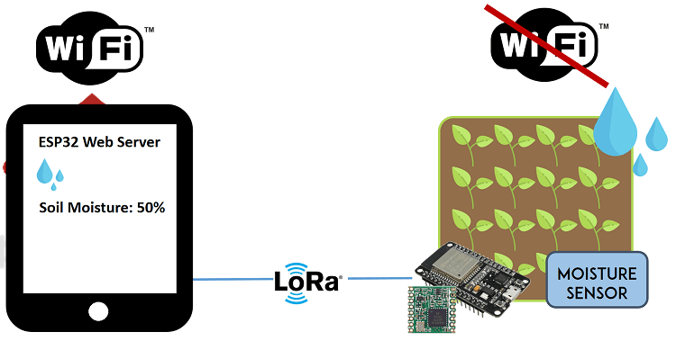
This is just an example that illustrates how you can use the LoRa technology in your ESP32 projects.
Note: we teach how to build this project on our “Learn ESP32 with Arduino IDE” course. It is Project 4 on the Table of Contents: LoRa Long Range Sensor Monitoring – Reporting Sensor Readings from Outside: Soil Moisture and Temperature. Check the course page for more details.

ESP32 with LoRa
In this section we’ll show you how to get started with LoRa with your ESP32 using Arduino IDE. As an example, we’ll build a simple LoRa Sender and a LoRa Receiver.
The LoRa Sender will be sending a “hello” message followed by a counter for testing purposes. This message can be easily replaced with useful data like sensor readings or notifications.

To follow this part you need the following components:
- 2x ESP32 DOIT DEVKIT V1 Board
- 2x LoRa Transceiver modules (RFM95)
- RFM95 LoRa breakout board (optional)
- Jumper wires
- Breadboard or stripboard
Alternative:
Instead of using an ESP32 and a separated LoRa transceiver module, there are ESP32 development boards with a LoRa chip and an OLED built-in, which makes wiring much simpler. If you have one of those boards, you can follow: TTGO LoRa32 SX1276 OLED Board: Getting Started with Arduino IDE.

You can use the preceding links or go directly to MakerAdvisor.com/tools to find all the parts for your projects at the best price!

Preparing the Arduino IDE
There’s an add-on for the Arduino IDE that allows you to program the ESP32 using the Arduino IDE and its programming language. Follow one of the next tutorials to prepare your Arduino IDE to work with the ESP32, if you haven’t already.
- Windows instructions – ESP32 Board in Arduino IDE
- Mac and Linux instructions – ESP32 Board in Arduino IDE
Installing the LoRa Library
There are several libraries available to easily send and receive LoRa packets with the ESP32. In this example we’ll be using the arduino-LoRa library by sandeep mistry.
Open your Arduino IDE, and go to Sketch > Include Library > Manage Libraries and search for “LoRa“. Select the LoRa library highlighted in the figure below, and install it.

Getting LoRa Tranceiver Modules
To send and receive LoRa messages with the ESP32 we’ll be using the RFM95 transceiver module. All LoRa modules are transceivers, which means they can send and receive information. You’ll need 2 of them.
You can also use other compatible modules like Semtech SX1276/77/78/79 based boards including: RFM96W, RFM98W, etc…
Alternatively, there are ESP32 boards with LoRa and OLED display built-in like the ESP32 Heltec Wifi Module, or the TTGO LoRa32 board.

Before getting your LoRa transceiver module, make sure you check the correct frequency for your location. You can visit the following web page to learn more about RF signals and regulations according to each country. For example, in Portugal we can use a frequency between 863 and 870 MHz or we can use 433MHz. For this project, we’ll be using an RFM95 that operates at 868 MHz.
Preparing the RFM95 Transceiver Module
If you have an ESP32 development board with LoRa built-in, you can skip this step.
The RFM95 transceiver isn’t breadboard friendly. A common row of 2.54mm header pins won’t fit on the transceiver pins. The spaces between the connections are shorter than usual.

There are a few options that you can use to access the transceiver pins.
- You may solder some wires directly to the transceiver;
- Break header pins and solder each one separately;
- Or you can buy a breakout board that makes the pins breadboard friendly.
We’ve soldered a header to the module as shown in the figure below.

This way you can access the module’s pins with regular jumper wires, or even put some header pins to connect them directly to a stripboard or breadboard.
Antenna
The RFM95 transceiver chip requires an external antenna connected to the ANA pin.

You can connect a “real” antenna, or you can make one yourself by using a conductive wire as shown in the figure below. Some breakout boards come with a special connector to add a proper antenna.

The wire length depends on the frequency:
- 868 MHz: 86,3 mm (3.4 inch)
- 915 MHz: 81,9 mm (3.22 inch)
- 433 MHz: 173,1 mm (6.8 inch)
For our module we need to use a 86,3 mm wire soldered directly to the transceiver’s ANA pin. Note that using a proper antenna will extend the communication range.
Important: you MUST attach an antenna to the module.
Wiring the RFM95 LoRa Transceiver Module
The RFM95 LoRa transceiver module communicates with the ESP32 using SPI communication protocol. So, we’ll use the ESP32 default SPI pins. Wire both ESP32 boards to the corresponding transceiver modules as shown in the next schematic diagram:

Here’s the connections between the RFM95 LoRa transceiver module and the ESP32:
- ANA: Antenna
- GND:
GND - DIO3: don’t connect
- DIO4: don’t connect
- 3.3V:
3.3V - DIO0:
GPIO 2 - DIO1: don’t connect
- DIO2: don’t connect
- GND: don’t connect
- DIO5: don’t connect
- RESET: GPIO 14
- NSS: GPIO 5
- SCK: GPIO 18
- MOSI: GPIO 23
- MISO: GPIO 19
- GND: don’t connect
Note: the RFM95 transceiver module has 3 GND pins. It doesn’t matter which one you use, but you need to connect at least one.
For practical reasons we’ve made this circuit on a stripboard. It’s easier to handle, and the wires don’t disconnect. You may use a breadboard if you prefer.

The LoRa Sender Sketch
Open your Arduino IDE and copy the following code. This sketch is based on an example from the LoRa library. It transmits messages every 10 seconds using LoRa. It sends a “hello” followed by a number that is incremented in every message.
/*********
  Rui Santos & Sara Santos - Random Nerd Tutorials
  Modified from the examples of the Arduino LoRa library
  More resources: https://RandomNerdTutorials.com/esp32-lora-rfm95-transceiver-arduino-ide/
*********/

#include <SPI.h>
#include <LoRa.h>

//define the pins used by the transceiver module
#define ss 5
#define rst 14
#define dio0 2

int counter = 0;

void setup() {
  //initialize Serial Monitor
  Serial.begin(115200);
  while (!Serial);
  Serial.println("LoRa Sender");

  //setup LoRa transceiver module
  LoRa.setPins(ss, rst, dio0);

  //replace the LoRa.begin(---E-) argument with your location's frequency
  //433E6 for Asia
  //868E6 for Europe
  //915E6 for North America
  while (!LoRa.begin(868E6)) {
    Serial.println(".");
    delay(500);
  }
   // Change sync word (0xF3) to match the receiver
  // The sync word assures you don't get LoRa messages from other LoRa transceivers
  // ranges from 0-0xFF
  LoRa.setSyncWord(0xF3);
  Serial.println("LoRa Initializing OK!");
}

void loop() {
  Serial.print("Sending packet: ");
  Serial.println(counter);

  //Send LoRa packet to receiver
  LoRa.beginPacket();
  LoRa.print("hello ");
  LoRa.print(counter);
  LoRa.endPacket();

  counter++;

  delay(10000);
}
Let’s take a quick look at the code.
It starts by including the needed libraries.
#include <SPI.h>
#include <LoRa.h>
Then, define the pins used by your LoRa module. If you’ve followed the previous schematic, you can use the pin definition used in the code. If you’re using an ESP32 board with LoRa built-in, check the pins used by the LoRa module in your board and make the right pin assignment.
#define ss 5
#define rst 14
#define dio0 2
You initialize the counter variable that starts at 0;
int counter = 0;In the setup(), you initialize a serial communication.
Serial.begin(115200);
while (!Serial);
Set the pins for the LoRa module.
LoRa.setPins(ss, rst, dio0);And initialize the transceiver module with a specified frequency.
while (!LoRa.begin(868E6)) {
  Serial.println(".");
  delay(500);
}
You might need to change the frequency to match the frequency used in your location. Choose one of the following options:
- 433E6
- 868E6
- 915E6
LoRa transceiver modules listen to packets within its range. It doesn’t matter where the packets come from. To ensure you only receive packets from your sender, you can set a sync word (ranges from 0 to 0xFF).
LoRa.setSyncWord(0xF3);Both the receiver and the sender need to use the same sync word. This way, the receiver ignores any LoRa packets that don’t contain that sync word.
Next, in the loop() you send the LoRa packets. You initialize a packet with the beginPacket() method.
LoRa.beginPacket();You write data into the packet using the print() method. As you can see in the following two lines, we’re sending a hello message followed by the counter.
LoRa.print("hello ");
LoRa.print(counter);
Then, close the packet with the endPacket() method.
LoRa.endPacket();After this, the counter message is incremented by one in every loop, which happens every 10 seconds.
counter++;
delay(10000);
Testing the Sender Sketch
Upload the code to your ESP32 board. Make sure you have the right board and COM port selected.
After that, open the Serial Monitor, and press the ESP32 enable button. You should see a success message as shown in the figure below. The counter should be incremented every 10 seconds.

The LoRa Receiver Sketch
Now, grab another ESP32 and upload the following sketch (the LoRa receiver sketch). This sketch listens for LoRa packets with the sync word you’ve defined and prints the content of the packets on the Serial Monitor, as well as the RSSI. The RSSI measures the relative received signal strength.
/*********
  Rui Santos & Sara Santos - Random Nerd Tutorials
  Modified from the examples of the Arduino LoRa library
  More resources: https://RandomNerdTutorials.com/esp32-lora-rfm95-transceiver-arduino-ide/
*********/

#include <SPI.h>
#include <LoRa.h>

//define the pins used by the transceiver module
#define ss 5
#define rst 14
#define dio0 2

void setup() {
  //initialize Serial Monitor
  Serial.begin(115200);
  while (!Serial);
  Serial.println("LoRa Receiver");

  //setup LoRa transceiver module
  LoRa.setPins(ss, rst, dio0);

  //replace the LoRa.begin(---E-) argument with your location's frequency
  //433E6 for Asia
  //868E6 for Europe
  //915E6 for North America
  while (!LoRa.begin(868E6)) {
    Serial.println(".");
    delay(500);
  }
   // Change sync word (0xF3) to match the receiver
  // The sync word assures you don't get LoRa messages from other LoRa transceivers
  // ranges from 0-0xFF
  LoRa.setSyncWord(0xF3);
  Serial.println("LoRa Initializing OK!");
}

void loop() {
  // try to parse packet
  int packetSize = LoRa.parsePacket();
  if (packetSize) {
    // received a packet
    Serial.print("Received packet '");

    // read packet
    while (LoRa.available()) {
      String LoRaData = LoRa.readString();
      Serial.print(LoRaData);
    }

    // print RSSI of packet
    Serial.print("' with RSSI ");
    Serial.println(LoRa.packetRssi());
  }
}
This sketch is very similar to the previous one. Only the loop() is different.
You might need to change the frequency and the sycnword to match the one used in the sender sketch.
In the loop() the code checks if a new packet has been received using the parsePacket() method.
int packetSize = LoRa.parsePacket();If there’s a new packet, we’ll read its content while it is available.
To read the incoming data you use the readString() method.
while (LoRa.available()) {
  String LoRaData = LoRa.readString();
  Serial.print(LoRaData);
}
The incoming data is saved on the LoRaData variable and printed in the Serial Monitor.
Finally, the next two lines of code print the RSSI of the received packet in dB.
Serial.print("' with RSSI ");
Serial.println(LoRa.packetRssi());
Testing the LoRa Receiver Sketch
Upload this code to your ESP32. At this point you should have two ESP32 boards with different sketches: the sender and the receiver.
Open the Serial Monitor for the LoRa Receiver, and press the LoRa Sender enable button. You should start getting the LoRa packets on the receiver.

Congratulations! You’ve built a LoRa Sender and a LoRa Receiver using the ESP32.
Taking It Further
Now, you should test the communication range between the Sender and the Receiver on your area. The communication range greatly varies depending on your environment (if you live in a rural or urban area with a lot of tall buildings). To test the communication range you can add an OLED display to the LoRa receiver and go for a walk to see how far you can get a communication (this is a subject for a future tutorial).

In this example we’re just sending an hello message, but the idea is to replace that text with useful information.
Wrapping Up
In summary, in this tutorial we’ve shown you the basics of LoRa technology:
- LoRa is a radio modulation technique;
- LoRa allows long-distance communication of small amounts of data and requires low power;
- You can use LoRa in point to point communication or in a network;
- LoRa can be especially useful if you want to monitor sensors that are not covered by your Wi-Fi network and that are several meters apart.
We’ve also shown you how to build a simple LoRa sender and LoRa receiver. These are just simple examples to get you started with LoRa. We’ll be adding more projects about this subject soon, so stay tuned!
You may also like reading:
- [Review] TTGO LoRa32 SX1276 OLED: Pinout, Specifications, etc…
- [Guide] TTGO LoRa32 SX1276 OLED Board: Getting Started with Arduino IDE
This is an excerpt from our course: Learn ESP32 with Arduino IDE. If you like ESP32 and you want to learn more, we recommend enrolling in Learn ESP32 with Arduino IDE course.
Thanks for reading.


LoRa article is super, I love it
Thanks 🙂
hello sara
i want use esp32 as lora gateway for The Things network ,Do u help me?
thanks vm
Hi.
I’m sorry, but at the moment, we don’t have any tutorial with TTN.
Regards,
Sara
can we do it using Sx1262?
Another great article, Rui. Thank you!
Thank you
Great tutorial, thank you so much.
i was try this project, and the result is okay but the range of the communication just lesst than 4 m? why the result like this? thanks you
Hello Rui, can I use nodemcu in place of esp32?
Hi.
We have just tested the examples with the ESP32 (but I think it should work with the ESP8266).
If it doesn’t work you can use the RadioHead library with a few modifications in the code.
Thanks Rui, for a very well documented project :-). I will need to jig the code to use RS232 LoRa radios!
Thanks 🙂
Nice.
Working through your course. Love it. Thanks. Do you have a Fritzing object for the ESP32? The ones on the forum are for a different board then the one you recommended ( Geekcreit® ESP32 Development Board from Banggood). I have the DEV1 board with 18 pins on each side. Also, this board does not fit a standard breadboard (to wide). I am going to solder to a PCB, but was wondering if you had any other suggestions that were less permanent.
Hi Kevin.
I have a suggestion for a less permanent solution to make the ESP32 breadboard friendly.
Usually breadboards come with two power rails on each side. Get two breadboards.
Remove one power rail per breadboard.
Then you can fit your ESP32 between the two breadboards and have plenty of space to connect your components.
I hope this helps.
(We have a part for the ESP32. I’ve designed it myself. But it is really bad designed to use in Fritzing. I don’t recommend using it, as you need to make some hacks later to design the schematics.)
Regards,
Sara 🙂
I cut the breadboard in two with a saw. It works perfect at no price….
thanks for the article. But how to crate a point to point communication to 3 Esp32? the first esp32 has a sensor attached to it and its capable of sending data to the second esp32, then the second esp32 must receive the data from the first esp32 then send it again to the third esp32. but I’m stuck on my second esp32 because i can’t figure it out how can i send the data to the third one. can anyone help me about this? please.
Hi.
We don’t have any tutorial about that subject.
But, I think you may find useful taking a look at the “LoRa Duplex communication with callback” example on the LoRa library.
In your Arduino IDE, go to File > Examples > LoRa > LoRaDuplexCallback.
That example sets both a receiver and a transmitter on the same esp32 (you probably need to do this for your second esp32). This code uses a callback to detect incoming messages.
I hope you find this tips useful.
Good luck with your project.
Regards,
Sara 🙂
How would you compare this to other wireless options like the nrf24l01 ?
I would appreciate your thoughts. Some points of comparison are battery consumption, ability to tolerate many units close together, and program ability and stability.
Thanks in advance
John
Hi John,
Both options are good and have different applications.
I recommend using LoRa for projects that need to cover a long range.
In terms of battery both boards should be fairly similar, but only testing in your specific scenario and code will give you accurate results.
Regards,
Rui
Why ESP32?
Couldn’t any micro be used such as UNO or even Raspberry Pi or ESP8266?
Ralph
You’re right. You could use any other board with these LoRa modules. In fact, I’ll be publishing tutorials using LoRa with Raspberry Pi in the future.
I’m just using the ESP32, because of it’s Wi-Fi capabilities and low price, but the ESP8266 would also be a good alternative.
Regards,
Rui
I am looking into using these, but lets say I have 3 devices, could I set the sync word all to be the same and then just use something in the packets to say its from x or y like LoRa.print(“10: hello”); LoRa.print(“10: world”); where 10 is the device sending. I am basically trying to make it so if i have a LoRa come in reach of another one they talk to each other, and if i had let’s say 5, they could all blast each other. I haven’t tried these yet but if you have any suggestions that would be awesome to get me going on something.
Hi Scott.
I haven’t tried it, but I think you can use the same syncword to all devices and then, change the message accordingly to the device that sent the message.
For example, device 1 sends something like this: “1/hello”.
Then, you can split that message to save which device sent the message.
Something as follows to split the message:
int pos1 = LoRaData.indexOf(‘/’);
device = LoRaData.substring(0, pos1);
message = LoRaData.substring(pos1 +1, LoRaData.length());
I hope this helps in your future project.
Regards,
Sara
Hello, when I use the commands Loradata. Substring, I have an error, it does not know this command, should we download another library?
Hi Arthur.
What error do you get?
I have an error in this line : captID = LoRaData.substring(0,pos1);
My error is :
exit status 1
‘LoRaData’ was not declared in this scope
there is an error with the LORADATA.
I found the solution,it is a mistake of my part.thank you
Hi, I’m using Heltec Wifi Lora kit with your code to test the communication between them. It managed to send and received the data but only within the short range where LoRa supposely can transmit within a long range. Can I know how far that your ESP32 can transmitted the data?
Hi Naz.
With a very rudimentar antenna, we were able to transmit data between two esp32 boards 250 meters apart.
Regards,
Sara 🙂
More examples with MQTT integration… 😉
Hi Luis.
In the following example we show how to integrate ESP32 with Node-RED using MQTT:
https://randomnerdtutorials.com/esp32-mqtt-publish-subscribe-arduino-ide/
Regards,
Sara 🙂
can something custom other than 0 to 0xFF be set as syncword?
I was just wondering that 0 to 255 is not a huge range and in future when LoRa becomes common this range will not be enough to isolate devices.
Hi.
That’s how the library is configured at the moment.
However, other libraries may have a bigger range of sync words, or maybe you can modify the library yourself to include a bigger range.
Regards,
Sara
Sync word size can be set from 1 to 8 bytes (i.e. 8 to 64 bits) via SyncSize in RegSyncConfig
dear sir/ma’am
i am just beginner
i want to know that we can make some node with sensor and one gateway which connect through internet using wifi
sensor retrieve data using esp 32 and send to lora network and gateway we receive and send internet server
i want use multiple node
sorry bed english
please give me some advice
Hi.
We don’t have any free tutorial about that subject.
If you want to build an ESP32 web server that publishes sensor readings received via LoRa from other ESP32 boards, I recommend that you take a look at how to build an ESP32 web server to publish sensor readings. Then, take a look at the examples on the LoRa library. They provide simple examples on how to send and receive data.
Here are some resources:
– Arduino LoRa library: github.com/sandeepmistry/arduino-LoRa
– Publish sensor readings using ESP32 (instead of publishing DHT readings, publish your own readings received via LoRa): https://randomnerdtutorials.com/esp32-dht11-dht22-temperature-humidity-web-server-arduino-ide/
I hope this helps.
Regards,
Sara
I try to use the examples but i have a problen woth the library when it checks some version.
Because of that the sketch stay infinitely in the while
while (!LoRa.begin(866E6)) { Serial.println(“.”);
delay(500);
}
Hi Guillermo.
That means that it can’t initialize the LoRa module. It is probably not properly connected.
Make sure you double check all your connections.
Regards,
Sara
hi, do you know how to connect to a lorawan gateway? thanks
Hi.
I’m sorry, but we don’t have any tutorial about that subject.
Regards,
Sara
Hi, Blog’s Owner
I want to use LoRa ESP 32 to get data from sensor and send data to Receiver and I want to use Receiver to control relay to work.
Hi.
This example exchanges information between the sender and receiver.
You just need to modify the code to include the sensor readings and sen them in the packet to the receiver.
Then, on the receiver you just need to control the relay. You can learn more about how to control a relay here: https://randomnerdtutorials.com/guide-for-relay-module-with-arduino/ This guide is for the arduino, but it will work in the ESP32.
Regards,
Sara
hi,
i’m interested il LORA tech: my goal is to transmit from a lora tx to a number of different receivers so the question is how many receivers can i address?
the transmission is a simple of/off command.
thanks
Hi.
I think it depends on many factors. But I don’t really know the maximum number of receivers. You’ll have to try that in your specific example.
I’m sorry that I can’t help much.
Regards,
Sara
Hi Sara,
than ks for youe replay. i’ve read some docs on LORA and rfm chips, and it seems it is possible to set sync words, to couple transmitter and receiver chips, from 1 to 8 bytes long: do you know this?
regards
Hi Salvatore.
Yes, I talk about that in the tutorial. That way you only receive packets from your devices and ignore other devices in your surroundings.
Also, you can check the library we’re using to find more information, there are a couple of examples that may be useful for your projects: github.com/sandeepmistry/arduino-LoRa/tree/master/examples
Regards,
Sara
Thank you andvregards
Salvatore
Hi sarah,
how can I measure the consumption of ESP32 based HUZZAH32 board. is possible with a card to add by USB !!
is it possible to replace RFM95 with NRF24L01 ???
Hi Amira.
NRF24L01 uses a different communication protocol.
You need the RFM95 module for this tutorial.
I’m not sure what you mean by a “card to add by USB”.
Regards,
Sara
Hi sara,
i using RFM98 in shield dragino and ESP32, its not work. in serial monitor just print “……”
can you help me? i need for final exam. thankyou
Hi.
That is probably a connection problem.
The ESP32 is not able to initialize the LoRa transceiver module.
It is probably a wrong connection or insufficient power supply.
I hope this helps and good luck for your final exam.
Regards,
Sara
so.. what should I do? i dont understand, sorry
it works for me after adding comment (//), as follow
/*
// check version
uint8_t version = readRegister(REG_VERSION);
if (version != 0x12) {
return 0;
}
*/
in Lora.cpp
but don’t know any side effect, yet..
Hello,
I have TTGO T-Beam ESP32 868 Mhz with Gps Neo-M8N.
How can I send GPS data from TTGO by Wi fi or bluetooth to my smartphone with android ?
Hi.
I don’t have any tutorials about that subject at the moment.
Regards,
Sara
Great tutorial👍
Thanks 😀
I have sent data from one lora module to another and now i want to upload the data received by the next lora module to the cloud using esp32 nodemcu. how do i do it?
Hi.
You just need to connect the LoRa receiver to the internet and create an HTTP Client to send an HTTP POST REQUEST with the data you want.
Regards,
Sara
Is there no password or something like SSID?
How can the both Transceivers recognize each other?
Hi Alexander.
You can use a syncword to ensure you only receive packets from your sender.
Regards,
Sara
Really? Do you really mean, it can help?
There are only 256 syncwords.
Hello Sara,
I have a problem with the receiver. After a while it hangs up. I need to reset it to receive packets again. Did you encounter this problem ?
Thanks
Bernard
Hi Bernard.
I don’t know why it happens.
Maybe you can add a condition to check if the packet was received. And if it wasn’t, reset the ESP32 with
ESP.restart();
Regards,
Sara
Try to add a capacitor over the Vcc and GND pin near your EPS32 to have a more stable power.
Regards
Otto
Hello Otto,
thanks I will try that and let you know about. But I fear this will not solve the problem because i use a good stabilised and filtered PS for the esp32.
But lets try !!!
Bernard
Sara,
thanks for the command. I do a restart every 30 packets. This is NOT an elegant way, just a workaround 🙂
Bernard
Hello Bernanrd, I have the same problem! will try to see if I can solve the problem as you say.
Did you find another way to fix this?
Thanks,
Tomás.-
Hello Tomas,
Didn’t found a better solution and even with a reset of the board I still have the board to hang on. This is NOT trustable.
Sara
Is it same code for ESP 32 Lora wifi_Oled sx 1276.Seem to get sender running at first but when l add a receiver l got a header file error.
Any ideas
Nocks
Hi Nocks. Which exact error are you getting?
1.Error compliling for board Heltec WiFi LoRa 32(V2)
Exit status 1
And also the ESP 32 loRa WiFi board not showing indications
What exact error do you get?
Hi everyone ! I’m doing the tutorial as explained, but the only packets I receive are 1 bit long, with a very low RSSI -> example :
Packet size 1 Received packet ‘�’ with RSSI -122
Packet size 1 Received packet ” with RSSI -123
Packet size 1 Received packet ‘�’ with RSSI -122
Packet size 1 Received packet ‘H’ with RSSI -122
Packet size 1 Received packet ‘�’ with RSSI -122
Packet size 1 Received packet ‘�’ with RSSI -121
Packet size 1 Received packet ‘�’ with RSSI -122
Packet size 1 Received packet ‘�’ with RSSI -121
Packet size 1 Received packet ‘�’ with RSSI -123
Packet size 1 Received packet ‘�’ with RSSI -122
Packet size 1 Received packet ‘�’ with RSSI -122
Packet size 1 Received packet ‘�’ with RSSI -121
Packet size 1 Received packet ‘)’ with RSSI -122
Packet size 1 Received packet ” with RSSI -122
Packet size 1 Received packet ” with RSSI -122
Packet size 1 Received packet ‘�’ with RSSI -122
Packet size 1 Received packet ” with RSSI -121
Packet size 1 Received packet ‘�’ with RSSI -122
Packet size 1 Received packet ‘�’ with RSSI -122
Packet size 1 Received packet ‘I’ with RSSI -122
Packet size 1 Received packet ‘�’ with RSSI -122
It seems I’m reading noises… I’ve tried with two different RFM 95 (868MHz). I don’t have 2 esp32 so my receiver is an esp32, and the sender is an esp8266 (I use those pins ss 15, rst 16, dio0 5 (with the classic MISO/MOSI/SCK).
Do you have any idea about what is happening ?
Have a nice day !
Hi.
what’s the message that you are trying to send?
It may be some problem related with the antenna. Make sure you have a proper antenna on both boards and that they get enough power.
If you’re using syncwords, make sure you have the same syncword on both boards.
Regards,
Sara
October 28, 2019
Sara,
Not sure exactly how to contact you directly. May I please have an e-mail address for you? I sent a detailed e-mail to you or perhaps it went to Rui, more than a week ago and have not had a reply. It relates to the need to have some e-courses on LoRa. It’s a fantastic technology and more of us out here need to be working with it.
Thanks in advance…
Regards,
Bob Rader
Hi Bob.
If you sent an email to the support, Rui will receive those emails.
However, he receives a lot of emails every day, and it difficult to keep up with all the emails he receives. Nevertheless, he tries to answer all emails, but it can take some time.
At the moment, we don’t have any courses specifically about LoRa. We cover LoRa in our ESP32 course. There’s a Module and a Project about it. But it is not a dedicated LoRa course, so it should not be suitable for what you want to do.
Regards,
Sara
October 29, 2019
Sara, Thanks so much for your reply. I am a retired communications engineer having worked on the development of solid state communications systems in the early to mid 1960’s for NASA programs at MIT. When I recently learned about LoRa I became very excited with a new communications technology that improved on VHF/ UHF communications range by improving upon the receiver sensitivity rather than adding more power at the transmitter end.
I am now interested in doing more with the LoRa technology here in the United States. My interest is low power long range, low data rate communications. LoRa is currently the prime technology that I am aware of to allow such communications to happen. Therefore, this is driving my desire to master this communications protocol.
I have read all your articles on the ESP-32 and LoRa. I have put on order some TTGO LoRa SX1276 OLED transceiver modules to allow me to duplicate and build upon the sketches from your recent article. I hoping to receive them soon so I can continue.
I hope you and Rui and company can see that LoRa is a perfect technology for the future and furtherance of the IOT industry. With that said, I encourage you to think about a dedicated course encompassing this technology. It seems that it is very much needed, at least here in the US where the technology has not caught on as it has in Europe.
Best Regards, Bob
Hi Bob.
Thanks for sharing your thoughts about this subject.
We probably won’t make a dedicated LoRa course. At least, in a near future.
But, we plan to write some more tutorials about this subject.
What would you like to see covered about LoRa technology with the ESP32?
Regards,
Sara
Hello Sara,
Can you help with this product, to increase coverage !!
[15,81€]LoRa 868MHz SX1276 SX1278 Wireless Transmitter and Receiver RF Module E32-868T30D Long Range 1W UART Transceiver rf Module Module Board For Arduino from Electronics on banggood.com
Hi Bernard.
I’m sorry, but I’ve never experimented with that module.
Maybe this topic can help: https://github.com/sandeepmistry/arduino-LoRa/issues/90
Regards,
Sara
Nov. 6, 2019
Sara, Received the TTGO LoRa32 SX1276 OLED boards today. Went to install the ESP32 into board manager and receiving an error “Error downloading https://dl.espressif.com/dl/package_esp32_index.json“. Looking online and it looks like others are having same trouble installing ESP32.
Can you explain what is happening????
Thanks, Bob
In your last picture you have an oled attached for display information but neither the schematic or the code reflects that
Care to update with them?
many thanks
Nov. 9, 2019
Sara,
Regarding my comment made on Nov. 6, 2019, I have setup a new windows 10 computer and installed the latest version of the Arduino IDE (1.8.10). I was then able to install the TTGO LoRa32 OLED board and able to get the sender & receiver programs working correctly. I did, however, make the installation using a link from Github instead of the link to Espressif.
https://github.com/espressif/arduino-esp32/blob/master/docs/arduino-ide/boards_manager.md
Stable release link: https://raw.githubusercontent.com/espressif/arduino-esp32/gh-pages/package_esp32_index.json
As time permits, I will look at why there was a problem with my older Win-7 computer to install the TTGO board manager on it.
Regards, Bob Rader
Hello. Is possible to make ESP32 Wroom and RFM95 works like end device Node and connect to the TTN ??
Yes, it is possible.
But at the moment, we don’t have any tutorial about that.
Regards,
Sara
Hello,
I´m trying to connect an ESP32 LoRa Heltec to a Dragino Gateway, what can I do?
Thank you very much for this post. I just ordered some rfm95 modules from ebay to try your code. I am planning to use many nodes (rfm95 + arduino + LoRa Sender Sketch ) to send sensor data to 1 (one) LoRawan gateway (rfm95 + esp32 + LoRa Receiver Sketch). I think that some messages that reach Lora gateway (receiver) in the same time will be lost (???). Do you have any idea how to deal with such a situation ?
Thanks a lot
Zak
Hi Zakaria.
Thank you for your comment.
At the moment, I haven’t had the time to investigate further about that subject.
Regards,
Sara
Hey , I followed all the above mentioned steps but facing this error “Starting LoRa Failed” …. I rechecked all the connections everything seems fine….
Could it be that ESP32 cannot supply enough current for the SX1278 in TX mode ? Is there any need for level converters, like Arduino Mega…?
Hi.
Are you using a setup like ours? Or are you using a board with a built-in lora chip?
If you’re using a board with built-in LoRa chip, you need to know the LoRa chip pin assignment and change it accordingly in the code.
Regards,
Sara
I am using the same setup as your’s, Dev ESP32 kit and a separate LoRa chip.
So, that error is probably related with wiring.
There’s probably something wrong in your wiring. Check all the connections, sometimes one wire that looks good is not making a connection. So, check with a multimeter.
Otherwise, I don’t know what else the problem can be.
Regards,
Sara
April 2, 2020
Sara,
I would like to respond to Ace January 9, 2020 at 8:06 pm. I have a possible reason for Ace’s problem and this is a more general problem that others may be facing.
Recently, I started having the same type of problem. I consulted with Adolfo Mondragon an engineer in Juarez Mexico. He found that doing a copy & paste using the windows editor from articles on the internet left unidentified & hidden extraneous characters in the code. After some time or after some number of times through the Arduino compiler these extraneous characters started to cause the code to fail. In my case I started getting a 302 error message after some time even though it may have worked at first.
I suggest that this may be something others need to be aware of.
In our research, we found that the windows editor doing the cut & paste feature inserted these extraneous hidden characters. In my case I had to use a text editor that showed all characters. I then proceeded to delete the extraneous characters.
Hope this will help others…
Regards,
Bob Rader
Hi Bob.
Thanks for pointing that out.
To copy the code to your Arduino IDE, you should click on the “View raw code” button under the code section, and copy the code from there to avoid those issues.
Thanks for sharing that, many others might have the same problem.
Regards,
Sara
Can it connect and send data (lora + esp32) to (esp32 without lora) using wifi or accesspoint?
if possible, how about the tutorial?
Hi.
To send data between boards using wi-fi, you can read this tutorial:
https://randomnerdtutorials.com/esp32-client-server-wi-fi/
Regards,
Sara
I found out that if you are sending from a Heltec board (or maybe others) and receiving on a RFM95 equipped board using this code you need to make sure you use the same spreading factors.
Hi Carl.
Thanks for pointing that out.
Regards,
Sara
Can Lora Esp32 send data to Lorawan (accesspoint)?
if possible, how?
Hello Sara,
my setup isn’t working, yet (it can’t initialize the radio and therefore only prints dots), but I’m relatively convinced I know why.
I didn’t entirely follow your connection instructions, so I used other PINs. Normally I’d think that doesn’t matter as long as the ones actually used are correctly referenced in the source code.
But that only goes for those ones:
RESET: GPIO 14
NSS: GPIO 5
SCK: GPIO 18
But is it with these ones?
DIO0: GPIO 2
MOSI: GPIO 23
MISO: GPIO 19
Where do the PIN numbers come from? Are they hard-coded in the LORA library used? Because I cannot find any reference to them in the source code.
Hi Jens.
Yes, you can use other pins as long as they are referenced on the code.
GPIO 23 (MOSI), GPIO 19 (MISO) and GPIO 18(SCK) are the default SPI pins of the ESP32. That’s why they are not referred on the code – they are automatically assigned.
If you want to use other pins, you need to create an SPI instance on those pins.
Regards,
Sara
Still doesn’t work I’m afraid after using all the PINs you used. I’ll need to check everything from scratch on the next weekend.
But thanks for explaining the issue that definitely existed before using your setup and the nice tutorial!
Ok.
Then, let me know if you got it working.
Regards,
Sara
Hi Sara,
surprisingly I found some time yesterday and – I’ve made fire! 🙂
I used a new radio chip and connected that. I didn’t unplug the cables from the ESP, but reused them. So last time the problem definitely lied on the radio chip’s side.
I guess I either created a short circuit on the radio chip’s contacts while soldering or I spent too much time soldering and exposed parts to too much heat.
Either way it’s working now. I’ll make it a bit nicer on the weekend. In the end it needs to be smaller than it is now as it’s going to be a mailbox sensor. And it needs to be a bit more robust when the mailman is forcing something in there with full force the next time.
Thanks again for the nice tutorial!
Suggestion: Maybe you can add RSS capability to your website. I’m not a big fan of newsletters and that would be a very nice alternative.
Hi Jens.
I’m glad everything is working fine now.
When soldering chips, you need to be quick and don’t spend much time on each pin with the soldering iron, otherwise it may “burn” and you’ll only notice afterwards.
Thanks for the suggestion. You can add to your RSS reader, this feed: https://randomnerdtutorials.com/feed/
Regards,
Sara
Hi Sara,
yes, I already knew that (not to spent too much time at or near components), but I have a lack of routine when it comes to soldering.
Did you really just implement the RSS feed or was it there all the time?
Best regards,
Jens
Hi again.
We have it for a long time 🙂
Regards,
Sara
Hi Sara,
You answer: …if you want to use other pins, you need to create an SPI instance on those pins.
How is this achieved? Please could you provide an example of how to do this that includes how to bind this to the Lora library?
Hi.
I recommend taking a look at this tutorial to learn more about SPI: https://randomnerdtutorials.com/esp32-spi-communication-arduino/
Simply use:
//SPI LoRa pins
SPI.begin(SCK, MISO, MOSI, SS);
//setup LoRa transceiver module
LoRa.setPins(SS, RST, DIO0);
Regards,
Sara
Hi Rui and Sara,
First of all, thank you both so much for these tutorials. As a beginner to the world of electronics, I really appreciate how clearly you guys explain everything. I did want to ask you one question though. After using the LoRa library by sandeep mistry in the past, I came across the Radiohead libraries which can also be used for transmission of packets. It seems that when I use the Radiohead libraries on all devices, the RSSI is much stronger and I can get the packets over much larger distances! However, the Radiohead library does not like the ESP 32 and there are many strange unknown characters and errors that appear when I try to use it. I was wondering if you have tried to use the Radiohead library before, if you have heard of any problems like this with the ESP 32, and how I might fix it.
Thank you!!
Hello, congratulations for the great articles … Could you help me, I have to read 5 digital keys on a esp32 with display (visualizing the number of keys that are closed), these states must be transmitted to another esp32, every 3 minutes. This receiver esp32 should, according to the number of closed switches, activate a relay.
I live in Brazil AU915-928.
thank you
How to send esp32 camera image with lorawan.
Hi.
I don’t think that is possible,
Regards,
Sara
Lora is meant as Low Rate, Long Range, telemetry, no pictures !!
Hi Sara Santos,
I am using heltec ESP32 lora. My sender and receiver device both are heltec ESP32. I don’t want to use lora gateway device instead of that am using ESP32 as a receiver and received payloads sends to my cloud server. In this case I want to connect multiple lora sender with one lora receiver. So how to sync multiple ESP32 lora sender with one ESP32 lora receiver using sync word (LoRa.setSyncWord(0xF3);) ?
Hi,
I am trying to find out if it is possible to pair an ESP32-cam with a LoRa transceiver (RFM95) module?
I don’t want to send pictures but rather use the camera to take a picture of a water meter, process the image, and then send the meter reading via LoRa. Similar to this project that utilises an ESP32 (github.com/jomjol/AI-on-the-edge-device) but implementing radio via LoRa rather than WiFi. I have read this tutorial on adding the RFM95 module to the standard ESP32 but I am new to hardware and not sure that the pin assignments will be possible on the ESP32-cam board.
Any thoughts or advice would be much appreciated.
Thanks,
James
Hi.
To help you with the pin assignment, you may want to take a look at the ESP32-CAM pinout: https://randomnerdtutorials.com/esp32-cam-ai-thinker-pinout/
Regards,
Sara
Thanks Sara,
I have realised I have a lot to learn.
Also wanted to say thanks for the fantastic resource that you guys have made available – I think my starting point needs to be your electronics for beginners course!
Regards,
James
Hi.
You can probably start with the “Learn ESP32 with Arduino IDE” course: https://randomnerdtutorials.com/learn-esp32-with-arduino-ide/
Regards,
Sara
Thanks Sara, will check it out.
James,
I am also working on a water meter project, Lora is a good idea if the meter is too far away for your wifi. I have seen somewhere an article on image processing that could read the meter. I would be interested in collaborating with you and others on this. I tried sensing the rotating magnet in my meter with a hall effect device, but signal is too weak for my brand of meter.
Hi Curt,
I still need to investigate a bit more to see what is possible. The water meter is about 50m from house, very narrow access about ½ a meter underground, no power nearby, quite a lot of hurdles. There are some commercial products that would work but I can’t change the meter provided by the water company.
I am going to order a ESP32 and have a play around in spare time, if I get anywhere I will send a follow up post, more than happy to share findings.
Hi,
You can add an ESP32 to your setup to control LORA module. ESP32 CAM will do the image processing stuff and send the meter reading to ESP32 which will send the result via LORA.
Regards
Said
hi
for the range
esp32+ loga module what is the range that can be reached in a city?
and what is the best board in term of range
thank you!
Hi.
Honestly, I don’t known.
It depends on a lot of factors.
But there are a few settings you can change to try increasing the communication range: https://github.com/sandeepmistry/arduino-LoRa/issues/90
With the ESP32 + lora module shown in this tutorial, we got only 130 meters. But it greatly depends on the environment.
Regards,
Sara
In a city , with my experience, if you don’t have site view, I mean with your eye, no more than 300 meters.
thank you for the tutorial
im from Algeria north africa, i couldnt find any available gateway in my country, in order to build one what is the suitable frequency for my case?
it was mentioned that africa has the same frequency as europe i.e. 868mhz but for the table on lora-alliance website 868 is not covered in my country’s frequencies. any suggestions?
Hi.
If you’re looking for gateways, it is better to search on the TTN (The Things Network) website.
Regards,
Sara
hi sara!
i want to send data to my gateway without passing through the ttn!
i mean directly from the arduino to gateway to mqtt
is that possible ?
thanks
What’s the communication protocol that you’ll use in the ARduino?
sx1276 with lora library
Hi.
I have a Dragino outdoor gateway with several nodes connected. i want add my customised nodes also to the same gateway, Is there any tutorial that guides me to add the ra-02 node to my network??
If yes please guide me through that.
Hi.
Unfortunately, at the moment, we don’t have any tutorials about that subject.
Regards.
Sara
Hello,
I am now using multiple Lora ESP32 TTGO modules with the same Synchword to a ESP32 web server. Any future plans for an ESP32 project using LoRaWAN?
Thank You for great tutorials.
Hi.
We intend to create some LoraWAN projects next year.
Regards,
Sara
Hi Rui and Sara
Thanks for some great tutorials, really appreciate how you break down the code and explain what each section does. I have 2 x E32-915T20D Lora Long Range UART SX1276 modules but they use the Tx/Rx pins, not SPI. Does your course cover using serial communication rather than SPI?
I would like to use one module connected to either a Pro-Mini or ESP32 board to monitor a remote site on the farm, the other module I planed to connect to an ESP32 to make a bridge to my home network via WiFi. At a later stage I’ll add more stations.
Regards,
Andrew
Hi Andrew.
Unfortunately, our course doesn’t cover serial connection.
We also don’t have any free tutorial about that.
I’m sorry that I can’t help much.
Regards,
Sara
Sara and Rui,
I have Heltec esp32 LoRa boards and would like to send data from more than one board to a single HOME board Via LoRa. Here is part of the code I believe identifies the boards.
String outgoing; // outgoing message
byte localAddress = 0xBB; // address of this device
byte destination = 0xFD; // destination to send to
byte msgCount = 0; // count of outgoing messages
long lastSendTime = 0; // last send time
int interval = 2000; // interval between sends
I do not understand this. Could you help me with it? How do I identify which board is which.? This device, destination device. Does each board already have a identification or is it assigned in code? I’m confused. Complete code is in the Helec ESP32 LoRa folder Heltec.LoRa Multiple Communication.
Thanks
Ramey Douglas
Great tutorial as usual. I am fan of “RNT”.
On this line from the post: Both the receiver and the sender need to use the same sync word. This way, the receiver ignores any LoRa packets that don’t contain that sync word.
Question1 > Can The Receiver pick up more than one sender? If yes, will the sync word be key to identify sender?
Question2> How many senders can talk to one receiver? any number between 0-254?
Awesome tutorial!
Do you have the tutorial on the distance testing with OLED?
Thanks!
Hi.
This example prints the RSSI and a counter: https://randomnerdtutorials.com/ttgo-lora32-sx1276-arduino-ide/
It may help.
Regards,
Sara
Was about to ask the question regarding RSSI and here you go and answer it.
Thanks!
Hello dear professors.
Thanks to you I have solved many problems for the disabled.
But…
Am I wrong? Or is it his Achilles heel at home?
What is the best method for indoors?
Esp-Mesh?
Esp-NOW?
Other method?
Thank you very much and have a nice day!
@}-,-‘——–
Gianfranco
Hi Sara,
I have problems with SyncWord function.
I tested isyncword with one sender (Heltic ESP32 LORA) and two receiver (heltic). One receiver has the same syncword as the sender. This receiver works great. The other receiver did not show the data on OLED.
Next test: I changed the Heltic Sender with an ATmega328P Sender. The receiver with the Sender syncword get the packages and show the data on the OLED. But the other reveiver (Heltec) with different syncword shows the packages too. But wrong formatting.
Is the syntax of syncword on ATmega328P different from Heltic ESP32 Lora?
Where can I find smething more about Lora SyncWord?
I have some problems with parallel using of two Sender – Receiver Projects.
When I use the two parallel both data packages are mixed and the Heltec OLED screen shows the two mixed on the display.
How can I control that the data package from Sender 1 only goes to Receiver 1 and the package from Sender 2 only goes to Receiver 2?
Hi.
I think it is better to open an issue on the library github page.
Here is the link: https://github.com/sandeepmistry/arduino-LoRa/issues
I hope this helps.
Regards,
Sara
Hi Sarah & Rui: When I run these sketches on the TTGO LoRa32 – OLED V1 boards, everything works perfectly at first. However, after a “random” (sorry, I couldn’t resist :>)) period of between 30 minutes and 11 hours, the receiver device hangs up. The transmitter continues to run and after resetting the receiver, transmission and reception resumes for another unpredictable period. I have also run the sketches with the Heltec WiFi LoRa 32 (V2) with exactly the same result. In addition, the sketches from https://randomnerdtutorials.com/esp32-lora-sensor-web-server/ run well with both boards – for a while; then the receivers hang. Do you have any suggestions for me? Thanks…
Hi Richard.
I’m not sure how to solve that issue.
Some of our readers reported similar issues.
The workaround was to add a ESP.reset() to reset the board periodically before it hangs.
Alternatively, you can also try to post an issue in the library github page: https://github.com/sandeepmistry/arduino-LoRa/issues
Regards,
Sara
I have the same random problem. The reset do not solve the problem. The card continue to hang randomly. This make the system untrustable and then useless.
I have used esp_restart(). That resolves the issue if the restart interval is shorter than the variable time to hangup. For my application the interruption is acceptable but for some, it may not be OK. I opened an issue # 447 on GitHub. Thanks,
Wow this is really fantasy. Good day sara I have something similar I want to work on which will require the use of both esp 32 and LoRa…….This might go a long way in helping me……Thank you
really fantastic article as always. Thanks for the insights. You make it look so easy. Need to try setting up experimental LoRa devices for testing
Wonderful
Have you seen the ESP32 single channel gateway that people have been posting of late on the web?
I am asking as frankly I have tried but I can’t get it to work and always end back on your web pages for guidance on what I may be doing wrong.
Your explanations are always clear and well laid out but alas I am still far from getting there but not giving up .
Keep up the great work on your tutorials the are helpful to so many
Cheers Clive
Hi Sara,
I will one lcd and one Lora module connect togehter to one SPI bus.
I´m little confused about the connections.
The LCD has:
CS – Chip select
RST- Reset
D/C – ? what is this?
SCK – Clock
MOSI – Data for LCD
MISO – not connectet for LCD
The Lora module has:
DIO0 – DIO5 ? what is this?
SCK – Clock
RESET – RESET
NSS ? what is this?
MOSI – is this only for sending data?
MISO – and this only for receiving data?
Best regards
Stefan
Hi Stefan.
You can use the same pins for SPI in multiple devices as long as each device has its own CS (Chip select) pin. This means you can use the same MISO, MOSI, and CLK pins.
I think this might answer your question about the D/C pin: /forums.adafruit.com/viewtopic.php?f=47&t=51949
NSS is the same as chip select. Check all the names for SPI interfaces here on the “Interfaces” section: en.wikipedia.org/wiki/Serial_Peripheral_Interface
This explains a bit about the DIO pins: https://github.com/matthijskooijman/arduino-lmic#dio-pins
I hope this helps.
Regards,
Sara
Great article. I made my 2 xESP32 with SX1276 working at the first attempt without any problem.
I was just interested to find the explanation of the several commands available with the library Lora.h but din’t find anything yet.
Any useful link to understand all the commands?
Like………
LoRa.setSpreadingFactor (10);
LoRa.setSignalBandwidth (62.5E3);
Thank you
Hi.
You can explore some of the library examples and read the comments to better understand how everything works.
Here’s the link for the library: https://github.com/sandeepmistry/arduino-LoRa
Regards,
Sara
Hey I am using this code but I wanted to expand on by having wifi connect to the board and once it has connected it sends out a LoRa Packet and goes through how should I go about sending and receiving once wifi has made connection what kind of if statement
Hi.
This tutorial will help better understand how to deal with Wi-Fi function with the ESP32, which will be useful for your project: https://randomnerdtutorials.com/esp32-useful-wi-fi-functions-arduino/
Regards,
Sara
What I really don’tunderstand is why the receiver code uses a while-loop to receive the datapcket (the message)
// read packet
while (LoRa.available()) {
String LoRaData = LoRa.readString();
Serial.print(LoRaData);
}
if the receiving needs multiple iterations of the while-loop you would get
an output like this
my m
my message
my message is this
if the receiving is done within ONE iteration there would be no need for a while-loop
an if-condition would be sufficient.
additional the use of variable-type String causes memory problems
so it shouldn’t be used in a demo-code
best regards Stefan
Semi-Private or Encrypted Lora Point to Point –
Thanks for an amazing write-up! Lora is supposedly secure, however if someone else out there has your same 0 to 255 (0x00 to 0xFF) synchWord, then I’m guessing they can intercept, listen to, or decode all of your point to point Lora messages?
How does one make a point to point, somewhat private, Lora communication? Is the only way to accomplish this easily is to make an 8 byte synchWord and hope no one guesses it? I don’t see where there has been any encryption so far or ability to make the communication semi-private between two points. Additionally how does one prevent noise or bad data from someone else transmitting on the same Lora syncWord? Thanks.
Hi Jerry.
In that case, I would recommend using LoraWAN.
I think that issue is well discussed in this discussion: https://stackoverflow.com/questions/68141970/lora-point-to-point-communication
Regards,
Sara
How to Implement this in which i have 1 receiver and many transmitter, Like a Network, I am new to this so, I want YOUR guide please.
Also, in Library there is also a Gateway and Node example will that be my solution.
Hi ^^, I have a question, I can use rfm95 module with an arduino nano? I can use this tutorial? Its the same proccess? thank you for this types of tutorials, I apreciate your work.
-Diego from Ecuador
Hi.
I’m not sure if it is the best board for this module.
Check the library compatibility: https://github.com/sandeepmistry/arduino-LoRa#compatible-hardware
Regards,
Sara
Hi,
I used the your programs two heltec lora esp32 V2 devices. The sender part works as i shows initialization and sending packets. The receiver part gets stuck before initializing lora and prints (…). So it seems the issue here is connecting with a corresponding sender. Can you please comment where i am getting it wrong.
The connections i use are
#define sck 5
#define miso 19
#define mosi 27
#define ss 18
#define rst 14
#define dio0 26
Hi.
Check the pinout of your LoRa board and change the pin definitions as needed.
Usually, the place where you buy the board provides the pinout.
Regards,
Sara
I would like to use these boards with a max485 board so I can send information back and forth for a wireless rs485 bridge. How can I do this?
Buenas , se podría usar en el receptor la funcionalidad de comunicación Lora y la de wifi?. Me gustaría saber si se puede programar un script (en el receptor) para poder recibir paquetes Lora y después enviarlos por wifi.
¿Es compatible usar Lora y Wifi en el receptor Lora?
Muchas gracias!
Hola.
Sí, es possible.
See this example: https://randomnerdtutorials.com/esp32-lora-sensor-web-server/
Regards,
Sara
I want to save lora messages to sd card with ttgo lora32 v2 .
Hello,
Can we change the syncWord at runtime?
Thanks
Hi.
Yes, I think you can do that.
Regards,
Sara
Hello,
I have 2 ESP32, connected with Lora, I put the sync word for the first one to (0xF3) and the other one to (0x44), and tried to send some data from one to another and I found that somtimes I got the data and sometimes not. I was expecting not receiving any data.
I found this a weird behaviour. What do you think?
Thanks.
Hello Sara
Do you know how to send data beside string ?? I want to store multiple sensor data sent by the transmitter in a variable so I can forward the data to the next node via mqtt, but it’s all in the string form and combined together. How can I store the data received in an individual variable ?? like Temperature = T, Pressure = P, etc. Should I send the individual data multiple time’s in a loop or use some kind of string extractor ? or is there any other strategies ?? Thank you.
Hi.
You can send everything on the same String separated by special characters like /, &, %, for example. Then, on the receiver, you just need to split the string.
Or you can send a JSON string. Then, on the receiver deserialize the string to get the individual data.
Regards,
Sara
Hi Sara
Thank you so much for replying. I just look up your other post about sending BMP sensor with LoRa and found the strategy of putting special characters in the string. I used it and it went pretty well. Thank you for a the post. This blog is really helping me finishing my final project in university.
That’s great!
Thank you so much for following our work.
Regards,
Sara
Hello to both of you,
First, thanks for what you’re doing to the Arduino community. I love reading your tutorials. Always clear and well detailed.
I have 2 questions for you regarding LoRa and Esp8266. I think I ordered the wrong LoRa modules with a frequency I can’t use in my country (France). I ordered the SX1278 Lora 433MHz Ra-02 and the ra-01 Lora sx1278 433mhz.
– Did I do a mistake? Is it possible to force a frequency of 868MHz on these modules?
– Regarding the MOSI and the MISO, I found a website where wiring is inverted for the receiver and the transmitter? Are they in the same positions for both receiver and transmitter in your circuit with the ESP32 (D23 and D19)?
Thank you
Laurent
Just to let you know that it worked well using your way with the ESP32 and one of these LoRa modules I have (433 MHz). And I had to switch MISO and MOSI for the receiver. So:
– Would it be better to use a frequency of 866MHz or 433 is fine?
– Why changing positions for MISO and MOSI?
Thanks
Laurent
Hi SARA,
I have tested the code of one Heltec lora V2 module and another one is Combination of ESP32 DEV v1 and Ai Thinker LORA ra01 module ,sometimes the combination stops working , is the problem lies with SPI wires? As replacing the ESP32 with another Heltec Lora module seems to be working fine.
thanks
Niranjan
Sara,
Your writing style and technical knowledge are much appreciated.
I’m hoping you, or one of your readers might be able to demystify one of the other very common, inexpensive LoRa modules – the Reyax RYLR896. There are several articles out there showing how to make RYLR modules connect two distant devices.
I’m attempting to mix-n-match, using a heltec lora ESP32 dev kit v2 with oled to receive data from an ESP32 connected to a RYLR896 module.
The Heltec code is based on the Heltec example OLED_LORA_Receiver sketch.
The ESP32 with the RYLR sketch uses Hardware serial port 2 to send AT commands to the RYLR896, and doesn’t use a LoRa library.
So far, I’m not able to receive data on the heltec module that is sent by the RYLR896.
The RYLR896 Frequency Band, Spreading factor, Bandwidth, and coding rate are set at 915E6, SF7, 125kHz, and coding rate 1 (which appears to be CRC4/5). The “Preprogrammed Preamble” is set to 4.
Since the heltec receive sketch uses Lora.h, I used the following methods:
LoRa.setCodingRate4(4); //I believe this is CRC4/5
LoRa.setPreambleLength(128);// – have also tried 4,8,16,32,64
LoRa.setSignalBandwidth(125E3);
LoRa.setSpreadingFactor(7);
LoRa.setSyncWord(0);
The RYLR has settings for NetworkID and device Address – which seems to be a LoRaWAN thing, not lower level LoRa. network address is set to 0 (“public”), and I’m sending with a destination address of 0 (broadcast). I haven’t been able to find these setting on the Heltec Lora module. My guess is that the RYLR protocol is somewhere between LoRa and LoRaWAN, and some of the addressing features may steal bits from sx1276 registers. Seems like the Heltec LoRa module should be able to receive and decode packets from the RYLR896 if the above settings match…
I believe my remaining issues is that the Preamble settings don’t match up:
“Preprogrammed Preamble” with valid range 4-7 on the RYLR896 and Preamble length with valid range 6-65535 on the Heltec module implementation. The semtech datasheet says the preamble length should be set the same on Tx and RX or the window needs to be larger on the receiver than on the tx in order to decode it. How does Preprogrammed Preamble correlate to Preamble Length? I’ve tried setting the
The RYLRxxx modules are using proprietary point to point protocols. Are not compatible with standard LoRa devices.
reyax.com/upload/products_download/download_file/LoRa_AT_Command_RYLR998_RYLR498_EN.pdf
Good evening to all,
A little tip: if you want a flawless communication, add the “yield();” command right after the “int packetSize = LoRa.parsePacket();” command and this should solve the random “hang up” effect from the receiver.
Have a wonderful Christmas and a Happy New Year 2023!
Wyatt
Thanks for the suggestion.
Happy New Year.
Regards,
Sra
Hello Wyatt,
this is a f….. good new, I stopped all usage of LoRa because of that unstability sice 3 years. I will give a last chance to survive to my preceeding projects.
Thanks to you.
Happy Christmas.
Bernard
Yesssss, this is THE solution against random hang up. Thanks a lot…
Hello,
This project is realy great ! and in fact I used your code and modifie it to controle 1 led (brightness) with a potentiometer on the trasmitter side.
I wanted to exted my project and try to send 2 values – as a string and then convert them back to integers to control 2 leds on the receiver side with 2 potentiometer (PWM)…. I can’t manage to that. How do I send 2 values (as strings 0 – 255) and then on the trasmitter side convert them back to integers and control via PWM 2 led light- intensities ?
Hi.
There are many different ways to achieve that.
Take a look at how we’ve done it in this tutorial: https://randomnerdtutorials.com/esp32-lora-sensor-web-server/
Basically, we concatenate the values in a string separated by a special character that you know beforehand. In that example:
LoRaMessage = String(readingID) + “/” + String(temperature) + “&” + String(humidity) + “#” + String(pressure);
T
hen, on the receiver, we can split the string on the special characters to get the values we want:
String LoRaData = LoRa.readString();
// LoRaData format: readingID/temperature&soilMoisture#batterylevel
// String example: 1/27.43&654#95.34
Serial.print(LoRaData);
Then, to covert to integer, you just need to use the toInt() function: https://docs.arduino.cc/built-in-examples/strings/StringToInt
An alternative is to send your values in a JSON string. On the receiver side, convert it to a JSON object and get the values you want. Then, you just need to use the toInt() function to convert to int.
I hope this helps.
Regards,
Sara
Just amaning !!! Thank you very much Sara, I will try this and report back 😉
BTW – Such a great site ! very – very helpful !
When I uploaded the sender code and Run it I get the following
“ets Jun 8 2016 00:22:57
rst:0x1 (POWERON_RESET),boot:0x3 (DOWNLOAD_BOOT(UART0/UART1/SDIO_REI_REO_V2))
waiting for download”
Hi.
That means your board is not in flashing mode.
You may need to press the BOOT button. Additionally, check that you don’t have any peripherals connected to the RST pin or GPIO 0.
Regards,
Sara
Does anyone know if this tutorial works with the Heltec V3 development board? HTIT-WB32LAF? The V3 being the critical question.
(https://www.amazon.com/Development-Antenna-Arduino-LoraWan-Internet/dp/B07HJ49VN8/ref=sr_1_14?crid=26SXI46QSB5JF&keywords=lora&qid=1677334549&sprefix=lora%2Caps%2C96&sr=8-14)
This is such a nice straight forward tutorial I thought it would be great to start here to learn LoRa.
A Heltec board is shown in the tutorial so I though this might be a simple bring up.
Alas, I can’t get anything going. Using the example sender sketch , it never gets out of the LoRa.begin(915E6) loop. It returns 0 . Peering into the library, it’s a read of a version register expecting a x12 that it doesn’t get. It all hints at something fundamental.
I looked at the board’s schematic (https://resource.heltec.cn/download/WiFi_LoRa32_V3/HTIT-WB32LA(F)_V3_Schematic_Diagram.pdf ) and defined the pins I think correctly. I tried:
#define ss 8
#define rst 12
#define dio0 6
Because the schematic was little confusing, I also tried:
#define ss 13
#define rst 17
#define dio0 6
I know that pins in certain libraries needed to change with the V3 but I am a little lost in tracing through the libraries. The example implies the above 2 pins are the most important and are defined directly with the sketch so I thought I had a chance. There might be deeper issues I can’t get past if the libraries aren’t right.
I confirmed on another forum that the Heltec official examples do not yet work with their V3 device so I was wondering if that is the same case here.
Hi.
I’m not sure if that board is compatible with the library we’re using.
That board uses the SX1262 LoRa chip. The library we’re using says it’s compatible with Semtech SX1276/77/78/79
So, I’m not sure if the issue is related to that, or if you’re using the wrong pinout.
Regards,
Sara
Yes, it is more a library issue than just a pin issue. For folks who search and find their way here and that see my question on the Heltec V3 board …I solved my ‘get something’ going problem by using the RadioLib by jgromes. I have LoRa transmitting and receiving on these V3 boards now. Nice thing is their example in the RadioLib has a simple pin override line so you avoid some of the concern with finding the correct pin definitions. I simply used SX1262 radio = new Module(8, 14, 12, 13); and I was up and running.
That’s great.
I’m glad you made it work.
Thanks for sharing the solution.
Regards,
Sara
I ran into the same issue with the heltec v3 board. I did get that board communicating with a hoperf module, but for the life of me no matter which library module I use, I cannot change the spread factor from 7 (to 6, or 8-12) or they just stop communicating. Have you had any luck with that v3 board with different spread factors and if you have which library did you end up using??
And by the way, this is the tutorial that got me started, and Rui and Sara have done a great job with all of their tutorials.
Cheers,
Bryan
A great article. I had no experience in Arduino or coding. But I have done small electronic projects about 35 years ago. I have read and watched the improvements and usefulness in the IoT systems. I have experience in vibration monitoring and analysis. For my current job, I have proposed somethings to detect impacts from big rocks with vibration shock detection method. The last 3 days I learn about how to do it with sensors and LoRa modules. I know it can be done, but I didn’t know how to interface the units and coding.
So, after about 3 days learning now I am quite confident I can do it by myself. A great article like this helps newbies like me. Hopefully, I can get some good results from the project. I have already ordered RFM95W & ESP32 for this.
Thanks again for sharing this.
Hi Sara
I’ve put together the example sender sketch with an RFM69HC and an ESP32. The RFM69 is a 433mhz part (ham band in the US). I’m currently on my 3rd RFM69 part with no luck!!
The sketch compiles OK, ESP boots normally and I get the “Lora Sender” output on the serial monitor but then all I get is a series of “…… .” forever! I’m really confused by this (not my first ESP32 coding project by a long shot! ) so I could really use a hint or three 😉 Any Ideas? Thanks TOM
“”
More resources: https://randomnerdtutorials.com
*********/
#include <SPI.h>
#include <LoRa.h>
//define the pins used by the transceiver module
#define ss 5
#define rst 14
#define dio0 2
int counter = 0;
void setup() {
//initialize Serial Monitor
Serial.begin(115200);
while (!Serial);
Serial.println(“LoRa Sender”);
//setup LoRa transceiver module
LoRa.setPins(ss, rst, dio0);
//replace the LoRa.begin(—E-) argument with your location’s frequency
//433E6 for Asia
//866E6 for Europe
//915E6 for North America
LoRa.begin(433E6);
while (!LoRa.begin(433E6)) {
Serial.println(“.”);
delay(1000);
}
“”
Hi.
Are you using separate modules?
Double-check that they are wired properly.
If you’re using a board with built-in RFM module, you need to check the board pinout.
Also, check the pinout for the specific board you’re using, as you may need to choose different pins depending on the layout of your board.
Regards,
Sara
Hi sara
Iam trying to transmit and recieve the string in non blocking mode using WEMOS LOLIN32 LITE [ESP32 ] with sx1276 lora module, here i took two esp32 with lora module, one is sending hai msg with count and other is sending hello msg with count , transmission happening actively in both boards, but both boards are not recieving actively message loss happening ,i tried this using RTOS , here is the code i used ,same code with used in other board with string modification.
#include <LoRa.h>
#include <SPI.h>
#define ss 5
#define rst 14
#define dio0 2
int counter = 0;
void setup()
{
Serial.begin(115200);
while (!Serial)
;
Serial.println(“LoRa Sender”);
LoRa.setPins(ss, rst, dio0); // setup LoRa transceiver module
while (!LoRa.begin(868E6)) // 433E6 – Asia, 866E6 – Europe, 915E6 – North America
{
Serial.println(“.”);
delay(500);
}
LoRa.setSyncWord(0xA5);
Serial.println(“LoRa Initializing OK!”);
xTaskCreate(
rx,
“task1”,
1000,
NULL, 1, NULL);
xTaskCreatePinnedToCore(
tx,
“task2”,
1000,
NULL, 1, NULL,1);
}
void tx(void *arguments)
{ while(true){
Serial.print(“Sending packet: “);
Serial.println(counter);
LoRa.beginPacket(); // Send LoRa packet to receiver

uint8_t a=LoRa.print("hai");

 uint8_t b= LoRa.print(counter);

LoRa.endPacket();

Serial.println(a);

Serial.println(b);

// counter++;

// delay(10);
vTaskDelay(1000 / portTICK_PERIOD_MS); // Add a delay to allow other tasks to run
counter++;
}
// vTaskDelay(100 / portTICK_PERIOD_MS);
}
void rx(void *arguments)
{
while(true){
int packetSize = LoRa.parsePacket(); // try to parse packet
Serial.println(packetSize);
if (packetSize)
{
Serial.print("Received packet'");while (LoRa.available()) // read packet
{
String LoRaData = LoRa.readString();
Serial.print(LoRaData);
}
Serial.print("' with RSSI "); // print RSSI of packet
Serial.println(LoRa.packetRssi());
vTaskDelay(1000/ portTICK_PERIOD_MS); // Add a delay to allow other tasks to run
}
else
{
// Serial.print("not Received packet '");
vTaskDelay(1000 / portTICK_PERIOD_MS); // Add a shorter delay when there's no data to receive
}}
}
void loop()
{
}
help me to overcome this issue.
Hi,
Would you recommend working with the SX1262?
Hi Sara,
thanks for this short and easy to understand tutorial.
How can I read out the actual preamb of the transmitted package in detail?
Hii ,
thanks
How can I read out the actual preamb of the transmitted package in detail?
Very nice tutorial, congrats!
A tip: in order to have a proper solder on the LoRa module I used a ESP32S breakout board like this one: aliexpress.com/item/32819647099.html then soldered LoRa’s pins on the left side (the one where says RESET). I Also managed to solder a pin for the ground and the antenna (on the right side = IO0).
Hi Sara,
Can I use my existing Arduino Nano board instead of ESP32?
Thank you, and more power to you and your staff.
Best regatds,
Monico
Hi.
Yes. The library is also compatible with the Arduino board.
Make sure you check the pinout for the Arduino: github.com/sandeepmistry/arduino-LoRa?tab=readme-ov-file#semtech-sx1276777879-wiring
Regards,
Sara
can we use Sx1262 with ESP32 wroom32?
Hello Sara,
I tried to make this circuit with an esp8266 Wemos D1 Mini board with the declaration of these pins: https://randomnerdtutorials.com/esp8266-pinout-reference-gpios/
The ones corresponding to the SPI connection are connected correctly according to the Wemos D1 Mini pin diagram (SCLK, MISO, MOSI)
and
#define ss 15
#define rst 16
#define dio0 2
But both, in the transmitter and in the receiver through the serial port the only thing that is observed is “Noise” meaningless symbols
I checked the cable connections several times but everything was correct, I don’t understand what I could be doing wrong
When compiling and loading on the board it doesn’t give errors.
Any ideas?
Thanks
Jesus
I’m running your sender code on a HiLetgo ESP32 LoRa SX1262 0.96 inch OLED with no problems. However, running the receiver code on a DOIT Devkit V1 with the SF95 LORA unit and an I2C 0.96 OLED, the code runs for some random length of time, from 30 minutes to 2 hours, then locks up. My SPI pin assignments are:
#define SCK 18
#define MISO 19
#define MOSI 23
#define SS 5
#define RST 12
#define DIO0 13
In setup() I can start LORA
//SPI LoRa pins
SPI.begin(SCK, MISO, MOSI, SS);
//setup LoRa transceiver module
LoRa.setPins(SS, RST, DIO0);
if (!LoRa.begin(BAND)) {

    delay(250) ;

    Serial.println("Starting LoRa failed!");

    while (1); // stop here
In loop(), as long as I don’t call LoRa.parsePacket() or LoRa.read(), the rest of the code runs fine. My conclusion is that after several hundred packets, something is going haywire in the library or the SPI driver. Anyone else see this? Are my SPI pin assignments a problem?
I published a solution some years ago, a line to add somewhere. But I don’t use esp32 anymore, too unstable, I prefer Raspi.
Obrigado pela partilha, vou experimentar esta montagem.
The ism band ranges are incorrect
Hi.
Can you tell me which ones?
Thank you.
Regards,
Sara
Hi,
Can I use raspberry pi pico as the tx side microcontroller and esp32 as rx side microcontroller does that cause any problems on sending and receiving data packets. Please provide your suggestions.
Hi.
Yes. You can use those boards without any problems.
Regards,
Sara
Thanks for replying,
Iam dealing with this issue that both boards are initialising lora and tx side is sending packets but the rx side is kept showing waiting for packets nothing other than that,can you help me over come this issue
Which LoRa module are you using?
Sx1278
Hello Mishab,
if you want someone to help you, please give more informations. Wiring of the pi and esp32 together and the wiring with sx1278, please join code in both of them.
Hi Sara, thanks for your work.
I made a test build with 2 ESP32 and 2 SX1276 boards, 86.3 mm antenna soldered.
I used the sender and receiver code without modification and the reiver shows messages like :
Received packet ‘m�dll�0’ with RSSI -64
Received packet ‘h�dl<,51’ with RSSI -65
Received packet ‘Z3ld_�=’ with RSSI -64
Is there a way to correct this ?
Regards,
Hubert
Hi.
In the section that receives and prints the messages, try printing one byte at a time instead
for (int i = 0; i < packetSize; i++) {
Serial.print((char)LoRa.read());
}
Let me know if this fixes the issue.
Regards,
Sara