This is a guide on how to interface the TM1637 4-Digit LED 7-Segment display with the ESP32 programmed with Arduino IDE. You’ll learn how to wire the display to the ESP32 and how to write characters. As an example, we’ll show you how to build a digital clock and a temperature display.

Table of Contents
In this tutorial, we’ll cover the following topics:
- Introducing the TM1637 4-Digit LED 7-Segment Display
- Wiring the TM1637 4-Digit 7-Segment Display to the ESP32
- Installing the TM1637 Library
- Testing the TM1637 Display (Basic Functions)
- Practical Examples with the TM1637 Display
Introducing the TM1637 4-Digit LED 7-Segment Display
The TM1637 4-Digit LED 7-Segment display is a display module that combines four 7-segment digits on a single display that can be controlled via the TM1637 driver. The particular module we’re using here has four digits separated by a colon between the second and third digits.

There are similar modules with dots between the digits.
There are also similar modules with six 7-segment digits. These require a different library from the one we’ll use in this tutorial.
Note: I tried to use my six 7-segment display module, but it seems that there are many of those displays that come faulty by default. I couldn’t make mine work. So, this tutorial will be only about the one with four digits with a colon in the middle.
Where to Buy?
You can check our Maker Advisor Tools page to compare the TM1637 4-Digit 7-Segment Display module price in different stores:
You can use the preceding links or go directly to MakerAdvisor.com/tools to find all the parts for your projects at the best price!

Wiring the TM1637 4-Digit 7-Segment Display to the ESP32

Wiring the display to the ESP32 is quite simple, as it only requires two digital pins: CLK and DI/O.
| TM1637 Display | ESP32 |
| CLK | Any digital pin (for example: GPIO 19)* |
| DIO | Any digital pin (for example: GPIO 18)* |
| VCC | VIN |
| GND | GND |
* you can use any other suitable GPIOs. Check the ESP32 Pinout Guide:
- ESP32 Pinout Reference: Which GPIO pins should you use?
- ESP32-S3 DevKitC Pinout Reference Guide: GPIOs Explained
We’ll connect the CLK pin to GPIO 19, and the DIO pin to GPIO 18, but you can use another combination of pins.

Installing the TM1637 Library
There are several libraries to interface the TM1637 display with the ESP32. We’ll use the TM1637.h library by avishorp (even though it hasn’t been updated for several years, it still works well, and it’s very easy to use).
You can install the library via the Arduino IDE library Manager. Search for TM1637 and install the library by avishorp.

Testing the TM1637 Display (Basic Functions)
The following code is the one provided by the library to test the display. You’ll figure out if your display is working properly and see how to implement the basic functions to initialize, control the display, and write characters.
/*
Rui Santos & Sara Santos - Random Nerd Tutorials
Complete project details at https://RandomNerdTutorials.com/esp32-tm1637-4-digit-7-segment-display-arduino/
Based on the TM1637Display library example: https://github.com/avishorp/TM1637/blob/master/examples/TM1637Test/TM1637Test.ino
*/
#include <Arduino.h>
#include <TM1637Display.h>
// Module connection pins (Digital Pins)
#define CLK 19
#define DIO 18
// The amount of time (in milliseconds) between tests
#define TEST_DELAY 2000
const uint8_t SEG_DONE[] = {
SEG_B | SEG_C | SEG_D | SEG_E | SEG_G, // d
SEG_A | SEG_B | SEG_C | SEG_D | SEG_E | SEG_F, // O
SEG_C | SEG_E | SEG_G, // n
SEG_A | SEG_D | SEG_E | SEG_F | SEG_G // E
};
TM1637Display display(CLK, DIO);
void setup()
{
}
void loop()
{
int k;
uint8_t data[] = { 0xff, 0xff, 0xff, 0xff };
uint8_t blank[] = { 0x00, 0x00, 0x00, 0x00 };
display.setBrightness(0x0f);
// All segments on
display.setSegments(data);
delay(TEST_DELAY);
display.showNumberDecEx(1230, 0b01000000);
delay(10000);
// Selectively set different digits
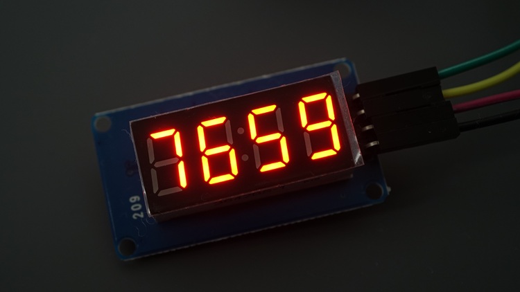
data[0] = display.encodeDigit(7);
data[1] = display.encodeDigit(6);
data[2] = display.encodeDigit(5);
data[3] = display.encodeDigit(9);
display.setSegments(data);
delay(TEST_DELAY);
/*
for(k = 3; k >= 0; k--) {
display.setSegments(data, 1, k);
delay(TEST_DELAY);
}
*/
display.clear();
display.setSegments(data+2, 2, 2);
delay(TEST_DELAY);
display.clear();
display.setSegments(data+2, 2, 1);
delay(TEST_DELAY);
display.clear();
display.setSegments(data+1, 3, 1);
delay(TEST_DELAY);
// Show decimal numbers with/without leading zeros
display.showNumberDec(0, false); // Expect: ___0
delay(TEST_DELAY);
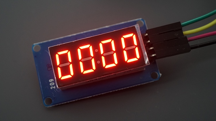
display.showNumberDec(0, true); // Expect: 0000
delay(TEST_DELAY);
display.showNumberDec(1, false); // Expect: ___1
delay(TEST_DELAY);
display.showNumberDec(1, true); // Expect: 0001
delay(TEST_DELAY);
display.showNumberDec(301, false); // Expect: _301
delay(TEST_DELAY);
display.showNumberDec(301, true); // Expect: 0301
delay(TEST_DELAY);
display.clear();
display.showNumberDec(14, false, 2, 1); // Expect: _14_
delay(TEST_DELAY);
display.clear();
display.showNumberDec(4, true, 2, 2); // Expect: 04__
delay(TEST_DELAY);
display.showNumberDec(-1, false); // Expect: __-1
delay(TEST_DELAY);
display.showNumberDec(-12); // Expect: _-12
delay(TEST_DELAY);
display.showNumberDec(-999); // Expect: -999
delay(TEST_DELAY);
display.clear();
display.showNumberDec(-5, false, 3, 0); // Expect: _-5_
delay(TEST_DELAY);
display.showNumberHexEx(0xf1af); // Expect: f1Af
delay(TEST_DELAY);
display.showNumberHexEx(0x2c); // Expect: __2C
delay(TEST_DELAY);
display.showNumberHexEx(0xd1, 0, true); // Expect: 00d1
delay(TEST_DELAY);
display.clear();
display.showNumberHexEx(0xd1, 0, true, 2); // Expect: d1__
delay(TEST_DELAY);
// Run through all the dots
for(k=0; k <= 4; k++) {
display.showNumberDecEx(0, (0x80 >> k), true);
delay(TEST_DELAY);
}
// Brightness Test
for(k = 0; k < 4; k++)
data[k] = 0xff;
for(k = 0; k < 7; k++) {
display.setBrightness(k);
display.setSegments(data);
delay(TEST_DELAY);
}
// On/Off test
for(k = 0; k < 4; k++) {
display.setBrightness(7, false); // Turn off
display.setSegments(data);
delay(TEST_DELAY);
display.setBrightness(7, true); // Turn on
display.setSegments(data);
delay(TEST_DELAY);
}
// Done!
display.setSegments(SEG_DONE);
while(1);
}
Let’s take a look at some of the relevant functions used in this example.
Initialize the Display
To initialize the display, you just need to create a TM1637Display instance with the pins you’re using to connect the module to your ESP32.
TM1637Display display(CLK, DIO);Set the Display Brightness
To set the brightness of the display, you can use the setBrightness() method on the display object. You can pass one or two arguments to this function.
void setBrightness(uint8_t brightness, bool on = true);The first is a number between 0 (min brightness) and 7 (max brightness), and the second argument sets the display on (true) or off (false).
In the code, this function is tested in the following snippet.
// Brightness Test
for(k = 0; k < 4; k++)
  data[k] = 0xff;
for(k = 0; k < 7; k++) {
  display.setBrightness(k);
  display.setSegments(data);
  delay(TEST_DELAY);
}

// On/Off test
for(k = 0; k < 4; k++) {
  display.setBrightness(7, false);  // Turn off
  display.setSegments(data);
  delay(TEST_DELAY);
  display.setBrightness(7, true); // Turn on
  display.setSegments(data);
  delay(TEST_DELAY);
}
Set Segments
The TM1637 display comes with four 7-segment display digits. You can manually control individual segments of each digit with the setSegments() function using an array of bytes.
void setSegments(const uint8_t segments[], uint8_t length = 4, uint8_t pos = 0);- segments: an array of bytes that defines which segments are ON for a digit. Each bit in the byte corresponds to one LED segment;
- length: how many digits to update (0 to 4) – this parameter is optional;
- pos: start position (0 – leftmost, 3 – rightmost) – the default is 0. This parameter is also optional.

How the Segments are Encoded
Each segment corresponds to a bit in the byte. Take a look at the following table:
| segment | bit |
| A | 0 |
| B | 1 |
| C | 2 |
| D | 3 |
| E | 4 |
| F | 5 |
| G | 6 |
Bit 1 turns a segment ON, and bit 0 turns a segment off.
For example, to turn on segments A, B, and C, you’d have a byte like 0b0000111.
The byte starts with the G and ends with the A. For example:
- 0b0000110 turns segments C and B on.
Display Specific Numbers or Characters
To display a specific number, you need to use the correct combination of segments:
- 0: a, b, c, d, e, f
- 1: b, c
- 2: a, b, g, e, d
- 3: a, b, g, c, d
- 4: f, g, b, c
- 5: a, f, g, c, d
- 6: a, f, g, e, d, c
- 7: a, b, c
- 8: a, b, c, d, e, f, g
- 9: a, b, c, d, f, g
With this, you can also display other characters, not only numbers.
For example, to manually encode 0123 in the display, you would need an array of bytes like so:
uint8_t segments[] = {
  0b0111111, // 0 — all segments except G
  0b0000110, // 1 — segments B and C
  0b1011011, // 2
  0b1001111  // 3
};
For example, to test this function, you can use the following code:
/*
  Rui Santos & Sara Santos - Random Nerd Tutorials
  Complete project details at https://RandomNerdTutorials.com/esp32-tm1637-4-digit-7-segment-display-arduino/
  Permission is hereby granted, free of charge, to any person obtaining a copy of this software and associated documentation files.
  The above copyright notice and this permission notice shall be included in all copies or substantial portions of the Software.
*/
#include <Arduino.h>
#include <TM1637Display.h>

#define CLK 19
#define DIO 18
TM1637Display display(CLK, DIO);

void setup() {
  display.setBrightness(7);

  // Custom segments (one byte per digit)
  uint8_t segments[] = {
    0b0111111, // 0 — all segments except G
    0b0000110, // 1 — segments B and C
    0b1011011, // 2
    0b1001111  // 3
  };

  display.setSegments(segments);
}

void loop() {

}
Display a Decimal Number
To display a decimal number, you can use the showNumberDec() function on the display object.
void showNumberDec(int num, bool leading_zero = false, uint8_t length = 4, uint8_t pos = 0);This function accepts the following parameters:
- num: the number to be shown
- leading_zero: when true, leading zeros are displayed. Otherwise, unnecessary digits are blank.
- length: the number of digits to set. The user must ensure that the number to be shown fits the number of digits requested (for example, if two digits are to be displayed, the number must be between 0 to 99)
- pos: the position of the most significant digit (0 – leftmost, 3 – rightmost)
There are several use case examples of this function in the code. The comments show what each command will display.
display.showNumberDec(0, false); // Expect: ___0
delay(TEST_DELAY);
display.showNumberDec(0, true);  // Expect: 0000
delay(TEST_DELAY);
display.showNumberDec(1, false); // Expect: ___1
delay(TEST_DELAY);
display.showNumberDec(1, true);  // Expect: 0001
delay(TEST_DELAY);
display.showNumberDec(301, false); // Expect: _301
delay(TEST_DELAY);
display.showNumberDec(301, true); // Expect: 0301
delay(TEST_DELAY);
display.clear();
display.showNumberDec(14, false, 2, 1); // Expect: _14_
delay(TEST_DELAY);
display.clear();
display.showNumberDec(4, true, 2, 2);  // Expect: 04__
delay(TEST_DELAY);
display.showNumberDec(-1, false);  // Expect: __-1
delay(TEST_DELAY);
display.showNumberDec(-12);        // Expect: _-12
delay(TEST_DELAY);
display.showNumberDec(-999);       // Expect: -999
delay(TEST_DELAY);
display.clear();
display.showNumberDec(-5, false, 3, 0); // Expect: _-5_
delay(TEST_DELAY);
Display a Decimal Number with a Colon/Dot
There is another function that allows you to display a decimal number and control whether the colon or dot (depending on the display) is on or off. That’s the showNumberDecEx() function. Here are the parameters accepted:
void showNumberDecEx(uint16_t num, uint8_t dots = 0, bool leading_zero = false, uint8_t length = 4, uint8_t pos = 0);It is similar to the previous showNumberDec() function, but the second argument allows us to enable or disable the colon/dot.
- num: the number to be shown
- dots: dot/colon enable – see below how it works
- leading_zero: when true, leading zeros are displayed. Otherwise, unnecessary digits are blank.
- length: the number of digits to set. The user must ensure that the number to be shown fits the number of digits requested (for example, if two digits are to be displayed, the number must be between 0 to 99)
- pos: the position of the most significant digit (0 – leftmost, 3 – rightmost)
Colon/dot control
The second argument of the showNumberDecEx() function is a bitmask, with each bit corresponding to a dot between the digits (or colon mark, as implemented by each module).
For example, for displays with dots between each digit:
- 0.000 > (0b10000000)
- 00.00 > (0b01000000)
- 000.0 > (0b00100000)
- 0.0.0.0 > (0b11100000)
In our case, it’s a display with just a colon. So, to display the colon, we can pass the following binary as a second argument:
- 00:00 > (0b01000000)
Finally, here’s an example for displays with dots and colons:
- 0.0:0.0 > (0b11100000)
For example, to display 12:30, you would call:
display.showNumberDecEx(1230, 0b01000000);In the code, this is where the function is used:
// Run through all the dots
for(k=0; k <= 4; k++) {
  display.showNumberDecEx(0, (0x80 >> k), true);
  delay(TEST_DELAY);
}
Demonstration
Upload the code to the board. It will display a series of digits, characters, and segments on the display to test the library functions.

If the example doesn’t work, double-check the wiring and the power supply.
Practical Examples with the TM1637 Display
Now that you know the basic functions to control the display, we’ll show you two practical examples that you can test with the TM1637 Display and the ESP32:
- ESP32 Digital Clock with the TM1637 Display (with timezone adjustment and DST)
- ESP32 Temperature Display (TM1637) — with temperature from WeatherAPI
These two projects only require the ESP32 and the display. No extra hardware is needed, as all the information will be requested from the internet using the ESP32’s Wi-Fi capabilities.
ESP32 Digital Clock with the TM1637 Display (with timezone adjustment and DST)
The layout of the TM1637 4-Digit 7-Segment display with a colon between the second and the third characters is ideal for creating a digital clock, with the hour on one side of the colon and the minutes on the other side.

We’ll get the time for your timezone using NTP (network time protocol) with adjustment for daylight saving time.
To learn more about getting time with the ESP32 for your timezone and consider daylight saving time (if that’s the case), you can read the following in-depth guide:
Project Overview
Here’s a quick overview of the steps to create this project:
- Initialize the display;
- Initialize Wi-Fi and connect the ESP32 to your local network so that it can get data from the internet;
- Initialize time for your specified timezone (takes into account daylight saving time);
- Show the time on the display (blink the colon between the numbers every second).
Code – TM1637 Digital Clock
You can upload the following code to your ESP32 board. You need to:
- Insert your SSID and password;
- Insert your timezone string. A list can be found on nayarsystems github’s.
/*
  Rui Santos & Sara Santos - Random Nerd Tutorials
  Complete project details at https://RandomNerdTutorials.com/esp32-tm1637-4-digit-7-segment-display-arduino/
  Permission is hereby granted, free of charge, to any person obtaining a copy of this software and associated documentation files.
  The above copyright notice and this permission notice shall be included in all copies or substantial portions of the Software.
*/
#include <WiFi.h>
#include "time.h"
#include <TM1637Display.h>

// Replace with your network credentials
const char* ssid     = "REPLACE_WITH_YOUR_SSID";
const char* password = "REPLACE_WITH_YOUR_PASSWORD";

// TM1637 pins
#define CLK 19
#define DIO 18

TM1637Display display(CLK, DIO);

// Timezone (Lisbon / Portugal)
// Change if needed - See list of timezones strings: https://github.com/nayarsystems/posix_tz_db/blob/master/zones.csv
const char* TZ_INFO = "WET0WEST,M3.5.0/1,M10.5.0";

// Init Wifi
void initWiFi() {
  WiFi.begin(ssid, password);
  while (WiFi.status() != WL_CONNECTED) {
    delay(1000);
    Serial.println("Connecting to WiFi..");
  }
}

// Initialize Time with the specified timezone
void initTime() {
  configTime(0, 0, "pool.ntp.org");
  setenv("TZ", TZ_INFO, 1);
  tzset();
}

// display the time on the screen
void displayTime() {

  // blinking colon
  static bool colon = false;
  colon = !colon;

  // get the current time
  struct tm timeinfo;
  if (!getLocalTime(&timeinfo)) {
    return;
  }

  int hours   = timeinfo.tm_hour;   // get hours (0–23)
  int minutes = timeinfo.tm_min;    // get minutes (0–59)

  // move hours to the left two digits
  int hourPart = hours * 100;

  // combine hours and minutes into HHMM
  int value = hourPart + minutes;

  // control the colon (for blinking colon)
  uint8_t colonMask;
  if (colon == true) {
    colonMask = 0b01000000;   // turn colon ON
  } else {
    colonMask = 0;            // turn colon OFF
  }

  display.showNumberDecEx(
    value,
    colonMask,   // blink colon
    true         // leading zeros
  );
}

void setup() {
  Serial.begin(115200);

  display.setBrightness(7);
  display.clear();

  initWiFi();
  initTime();
}

void loop() {
  displayTime();
  delay(1000);
}
How Does the Code Work?
Let’s take a quick look at the code to see how it works.
Include Libraries
Start by including the required libraries.
#include <WiFi.h>
#include "time.h"
#include <TM1637Display.h>
Network Credentials
Insert your network credentials on the following lines.
// Replace with your network credentials
const char* ssid     = "REPLACE_WITH_YOUR_SSID";
const char* password = "REPLACE_WITH_YOUR_PASSWORD";
Initialize the Display
Set the TM1637 pins and create an instance for the display called display.
// TM1637 pins
#define CLK 19
#define DIO 18

TM1637Display display(CLK, DIO);
Timezone
Insert your timezone string in the following line. You can find a list of timezone strings here. In my case, my timezone is Lisbon/Portugal, so it will look as follows:
const char* TZ_INFO = "WET0WEST,M3.5.0/1,M10.5.0";Initialize Wi-Fi
The following function initializes Wi-Fi and connects the ESP32 to your local network. This will be called later on in the setup().
// Init Wifi
void initWiFi() {
  WiFi.begin(ssid, password);
  while (WiFi.status() != WL_CONNECTED) {
    delay(1000);
    Serial.println("Connecting to WiFi..");
  }
}
You can learn more about the ESP32 Wi-Fi function in the following tutorial:
Initialize Time
The initTime() function initializes NTP time and adjusts it to your timezone—notice the setenv() and tzset() functions.
// Initialize Time with the specified timezone
void initTime() {
  configTime(0, 0, "pool.ntp.org");
  setenv("TZ", TZ_INFO, 1);
  tzset();
}
To learn more about getting the date and time with timezone adjustment, check out this tutorial:
The displayTime() function will display the date and time on the screen.
void displayTime() {We have a boolean variable called colon to determine whether the colon is showing up or not (to create the blinking effect).
// blinking colon
static bool colon = false;
colon = !colon;
We get the current time and save it in the timeinfo structure.
// get the current time
struct tm timeinfo;
if (!getLocalTime(&timeinfo)) {
  return;
}
Then, we can get the hour and minutes as follows:
int hours   = timeinfo.tm_hour;   // get hours (0–23)
int minutes = timeinfo.tm_min;    // get minutes (0–59)
Now, to display the numbers on the screen, we need to combine the date and time in a single number with four digits that will be split in the middle by the colon.
We can do that by multiplying the hour by 100 and then adding the minutes.
// move hours to the left two digits
int hourPart = hours * 100;

// combine hours and minutes into HHMM
int value = hourPart + minutes;
For example, imagine the hour is 12 and the minutes are 30. We want to get 12:30. So, we need to get the 1230 number and display the colon in the middle.
12*100+30 will give the desired 1230. This number is saved in the value variable.
Finally, we adjust the bitmask to display the colon depending on whether it is time to display the colon.
// control the colon (for blinking colon)
uint8_t colonMask;
if (colon == true) {
  colonMask = 0b01000000;   // turn colon ON
} else {
  colonMask = 0;            // turn colon OFF
}
We can use the showNumberDecEx() to display the time on the screen. Pass as an argument the value, the bit mask for the colon, and whether we have leading zeros.
display.showNumberDecEx(
  value,
  colonMask,   // blink colon
  true         // leading zeros
);
Now that we have all the essential functions declared, it is easy to set up our code.
setup()
In the setup() initialize the Serial Monitor, set the display brightness, initialize Wi-Fi, and time.
void setup() {
  Serial.begin(115200);

  display.setBrightness(7);
  display.clear();

  initWiFi();
  initTime();
}
loop()
Finally, in the loop(), you just need to call the displayTime() function to display the time on the 4-digit 7-segment display module.
void loop() {
  displayTime();
  delay(1000);
}
Demonstration
After inserting your network credentials and your timezone information, you can upload the code to the ESP32.
It should start displaying the current time for your timezone.

The colon should be blinking every second to resemble those old digital clocks.
ESP32 Temperature Display (TM1637) from Weather API
In this project, we’ll display the current temperature for your city on the display. We’ll get the temperature from the Weather API.
This API is free and provides useful information about the weather in almost any location in the world.

We’ll get the temperature for your location and display it on the 7-segment display module.
Getting Your API Key
- Go to the Weather API website: weatherapi.com/
- Signup to create an account.
- After verifying your account, login into your account.
- On your dashboard at weatherapi.com/my/ , you’ll find your API key (even though it says the trial will end, you can continue using your API key freely).

Copy the API key to a safe place because you’ll need it later.
To pull information on the weather in your chosen location, enter the following URL in your web browser, but insert your location and API key in the right places:
https://api.weatherapi.com/v1/current.json?q=YOUR_LOCATION+&key=YOUR_API_KEY'
For example, in my case:
https://api.weatherapi.com/v1/current.json?q=Oporto+&key=d1578a064b07453c917164350240106'Copy your URL and paste it into your browser, and the API will return information corresponding to your local weather. For example:
{
  "location": {
    "name": "Oporto",
    "region": "Porto",
    "country": "Portugal",
    "lat": 41.15,
    "lon": -8.62,
    "tz_id": "Europe/Lisbon",
    "localtime_epoch": 1719843562,
    "localtime": "2024-07-01 15:19"
  },
  "current": {
    "last_updated_epoch": 1719843300,
    "last_updated": "2024-07-01 15:15",
    "temp_c": 22.3,
    "temp_f": 72.1,
    "is_day": 1,
    "condition": {
      "text": "Sunny",
      "icon": "//cdn.weatherapi.com/weather/64x64/day/113.png",
      "code": 1000
    },
    "wind_mph": 10.5,
    "wind_kph": 16.9,
    "wind_degree": 310,
    "wind_dir": "NW",
    "pressure_mb": 1021,
    "pressure_in": 30.15,
    "precip_mm": 0,
    "precip_in": 0,
    "humidity": 69,
    "cloud": 0,
    "feelslike_c": 24.7,
    "feelslike_f": 76.4,
    "windchill_c": 21.9,
    "windchill_f": 71.5,
    "heatindex_c": 24.6,
    "heatindex_f": 76.2,
    "dewpoint_c": 15,
    "dewpoint_f": 58.9,
    "vis_km": 10,
    "vis_miles": 6,
    "uv": 6,
    "gust_mph": 15.4,
    "gust_kph": 24.7
  }
}
From this JSON, we can easily get the temperature for your location, either in Celsius or Fahrenheit: temp_c and temp_f.
Installing Libraries
For this example, you need to install the ArduinoJSON library by bblanchon.

Code – TM1637 Temperature Display
You can upload the following code to your board. You need to:
- insert your SSID and password;
- insert your WeatherAPI API key;
- insert the city where you want to get the temperature for.
/*
  Rui Santos & Sara Santos - Random Nerd Tutorials
  Complete project details at https://RandomNerdTutorials.com/esp32-tm1637-4-digit-7-segment-display-arduino/
  Permission is hereby granted, free of charge, to any person obtaining a copy of this software and associated documentation files.
  The above copyright notice and this permission notice shall be included in all copies or substantial portions of the Software.
*/
#include <WiFi.h>
#include <HTTPClient.h>
#include <ArduinoJson.h>
#include <TM1637Display.h>

// Wi-Fi credentials
const char* ssid = "REPLACE_WITH_YOUR_SSID";
const char* password = "REPLACE_WITH_YOUR_PASSWORD";

const char* api_key = "REPLACE_WITH_YOUR_WeatherAPI_API_Key";
const char* location = "Oporto";  // "q" Parameter documentation for location: https://www.weatherapi.com/docs/#intro-request

// Request URL
String url = "https://api.weatherapi.com/v1/current.json?q=" + String(location) + "&key=" + String(api_key);

// TM1637 pins
#define CLK 19
#define DIO 18

TM1637Display display(CLK, DIO);

// Create the °C Symbol
const uint8_t Celsius[] = {
  SEG_A | SEG_B | SEG_F | SEG_G,  // Circle
  SEG_A | SEG_D | SEG_E | SEG_F   // C
};

// Create the °F Symbol
const uint8_t Fahrenheit[] = {
  SEG_A | SEG_B | SEG_F | SEG_G,  // Circle
  SEG_F | SEG_E | SEG_A | SEG_G   // F
};

// Global variables for temperatures and timers
float currentTempC = 9999;  // Initial error value
float currentTempF = 9999;  // Initial error value
unsigned long lastFetchTime = 0;
const unsigned long fetchInterval = 3600000UL;  // 1 hour in milliseconds

// Init Wifi
void initWiFi() {
  WiFi.begin(ssid, password);
  while (WiFi.status() != WL_CONNECTED) {
    delay(1000);
    Serial.println("Connecting to WiFi..");
  }
  Serial.println("Connection successful");
  Serial.print("IP address: ");
  Serial.println(WiFi.localIP());
}

bool updateTemperatures() {
  HTTPClient http;
  http.begin(url);

  int httpCode = http.GET();

  if (httpCode == HTTP_CODE_OK) {  // Check for 200 specifically
    String payload = http.getString();
    Serial.print(payload);

    // Parse JSON
    StaticJsonDocument<1024> doc; // Adjust size if needed based on response
    DeserializationError error = deserializeJson(doc, payload);

    if (error) {
      Serial.print("JSON parsing failed: ");
      Serial.println(error.c_str());
      http.end();
      return false;
    }

    // Get both temperatures
    currentTempC = doc["current"]["temp_c"];
    currentTempF = doc["current"]["temp_f"];
    http.end();
    return true;
  } else {
    Serial.print("Error during request: ");
    Serial.println(httpCode);
    http.end();
    return false;
  }
}

void setup() {
  Serial.begin(115200);
  delay(1000); // Give time for Serial to initialize

  // Connect to Wi-Fi
  initWiFi();

  display.setBrightness(7);  // Set the display brightness (0-7)

  // Initial fetch
  if (updateTemperatures()) {
    lastFetchTime = millis();
  }
}

void loop() {
  // Check if it's time to fetch new data
  if (millis() - lastFetchTime >= fetchInterval) {
    if (updateTemperatures()) {
      lastFetchTime = millis();
    } else {
      // If failed, try again next loop
      Serial.println("Fetch failed, keeping old values.");
    }
  }

  // Show Celsius
  Serial.print("Temperature in Celsius: ");
  Serial.println(currentTempC, 2);

  int roundedTempC = round(currentTempC);
  display.showNumberDec(roundedTempC, false, 2, 0);
  display.setSegments(Celsius, 2, 2);

  delay(5000);

  // Show Fahrenheit
  Serial.print("Temperature in Fahrenheit: ");
  Serial.println(currentTempF, 2);

  int roundedTempF = round(currentTempF);
  display.showNumberDec(roundedTempF, false, 2, 0);
  display.setSegments(Fahrenheit, 2, 2);

  delay(5000);
}
How Does the Code Work?
Let’s take a quick look at the relevant parts of the code for this tutorial.
Including Libraries
We start by including the required libraries.
#include <WiFi.h>
#include <HTTPClient.h>
#include <ArduinoJson.h>
#include <TM1637Display.h>
Network Credentials
Insert your network credentials in the following lines.
// Replace with your network credentials
const char* ssid     = "REPLACE_WITH_YOUR_SSID";
const char* password = "REPLACE_WITH_YOUR_PASSWORD";
Weather API
Insert your WeatherAPI key and the location you want to get data for.
const char* api_key = "REPLACE_WITH_YOUR_API_KEY";
const char* location = "REPLACE_WITH_YOUR_LOCATION";
This is the request URL that will return the weather data.
String url = "https://api.weatherapi.com/v1/current.json?q=" + String(location) + "&key=" + String(api_key);TM1637 Display
Set the pins that are controlling the display and initialize an instance of the display called display.
// TM1637 pins
#define CLK 19
#define DIO 18

TM1637Display display(CLK, DIO);
Create an array with the required segments to create the ºC and ºF symbols.
// Create the °C Symbol
const uint8_t Celsius[] = {
  SEG_A | SEG_B | SEG_F | SEG_G,  // Circle
  SEG_A | SEG_D | SEG_E | SEG_F   // C
};

// Create the °F Symbol
const uint8_t Fahrenheit[] = {
  SEG_A | SEG_B | SEG_F | SEG_G,  // Circle
  SEG_F | SEG_E | SEG_A | SEG_G   // F
};
The SEG_A, SEG_B, and so on are references to their specific bytes (these are defined in the library .h file).
Global variables
Create global variables to store the temperature in Celsius and Fahrenheit.
float currentTempC = 9999;  // Initial error value
float currentTempF = 9999;  // Initial error value
And auxiliar variables to count the time to make a request to the API every hour.
unsigned long lastFetchTime = 0;
const unsigned long fetchInterval = 3600000UL;  // 1 hour in milliseconds
Initialize Wi-Fi
The initWiFi() function will initialize Wi-Fi and connect to your network using the inserted credentials.
// Init Wifi
void initWiFi() {
  WiFi.begin(ssid, password);
  while (WiFi.status() != WL_CONNECTED) {
    delay(1000);
    Serial.println("Connecting to WiFi..");
  }
  Serial.println("Connection successful");
  Serial.print("IP address: ");
  Serial.println(WiFi.localIP());
}
Get/Update the Temperatures
The updateTemperatures() function makes a request to the WeatherAPI request URL.
The request returns a bunch of weather data as we’ve seen previously. We print all data to the Serial Monitor.
bool updateTemperatures() {
HTTPClient http;
http.begin(url);

int httpCode = http.GET();

if (httpCode == HTTP_CODE_OK) {  // Check for 200 specifically
  String payload = http.getString();
  Serial.print(payload);
Then, we only save the data we’re interested in. In this case, the temperature in Celsius and Fahrenheit. We save them in the currentTempC and currentTempF variables.
currentTempC = doc["current"]["temp_c"];
currentTempF = doc["current"]["temp_f"];
If everything goes well with the request, the function returns true. Otherwise, it returns false.
setup()
In the setup(), we initialize the Serial Monitor, connect to Wi-Fi, and set the display brightness.
void setup() {
  Serial.begin(115200);
  delay(1000); // Give time for Serial to initialize

  // Connect to Wi-Fi
  initWiFi();

  display.setBrightness(7);  // Set the display brightness (0-7)
Then, we make our first request to the API to get the current temperatures when the code first runs. From that time on, we also start counting the time to check later in the loop() if it’s time to make another request.
// Initial fetch
if (updateTemperatures()) {
  lastFetchTime = millis();
}
loop()
In the loop(), we’re constantly checking when it’s time to get new values.
// Check if it's time to fetch new data
if (millis() - lastFetchTime >= fetchInterval) {
if (updateTemperatures()) {
lastFetchTime = millis();
} else {
// If failed, try again next loop
Serial.println("Fetch failed, keeping old values.");
}
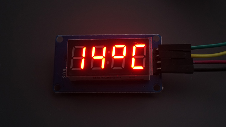
}Then, in the display, we’re alternating between showing the temperature in Celsius and in Fahrenheit every five seconds.
// Show Celsius
Serial.print("Temperature in Celsius: ");
Serial.println(currentTempC, 2);

int roundedTempC = round(currentTempC);
display.showNumberDec(roundedTempC, false, 2, 0);
display.setSegments(Celsius, 2, 2);

delay(5000);

// Show Fahrenheit
Serial.print("Temperature in Fahrenheit: ");
Serial.println(currentTempF, 2);

int roundedTempF = round(currentTempF);
display.showNumberDec(roundedTempF, false, 2, 0);
display.setSegments(Fahrenheit, 2, 2);

delay(5000);
Since the temperature values come as float variables, we need to convert them to integers. To do that, we use the round() function to round the number. For example:
int roundedTempC = round(currentTempC);Then, we simply call the showNumberDec() function to display the values.
display.showNumberDec(roundedTempC, false, 2, 0);Then, call the setSegments() function to display the ºC and ºF Units.
display.setSegments(Celsius, 2, 2);Demonstration
Upload the code to your ESP32 board. Don’t forget to insert your SSID and password in the code, as well as the API key, and your location.
You should get a successful message on the Serial Monitor.

And the temperature in Celsius and Fahrenheit degrees will show up alternating on the display.

Wrapping Up
This was a comprehensive guide on how to interface the TM1637 4-digit 7-segment display with the ESP32. It can be quite useful to display temperature, the time, or other information.
The specific format of display we have, with a colon in the middle, might be especially useful to create a digital clock or to display a timer.
We hope you’ve found this guide useful. We have guides for other displays that might be helpful:
- ESP32 OLED Display with Arduino IDE
- How to Use I2C LCD with ESP32 on Arduino IDE
- Getting Started with ESP32 Cheap Yellow Display Board – CYD (ESP32-2432S028R)
- ESP32: TFT LCD Touchscreen Display – 2.8 inch ILI9341 240×320 (Arduino IDE)
To learn more about the ESP32, make sure to check out our resources:


Hello, Tested ok. How much display can we connect to one esp32 considering power requirement ? Thanks for your infos, marc
Hi, from regular and happy visitor:
should you power the display from VIN?
TM1637 uses input voltage level as DIO output level.
Tm1637 library reads ACK from display. Officially ESP32 inputs are not 5V tolerant.
I’d love to hear your take on this.
Hi.
We didn’t have any issues with this configuration.
You can try to power it with the 3.3V pin instead. But, I’m not sure if this display works with 3.3V.
Regards,
Sara