In this guide, you’ll learn how to use software timers (timer interrupts) with the ESP32 using FreeRTOS programming on Arduino IDE. We’ll take a look at auto-reload (periodic) timers and one-shot timers, and provide simple examples so that you can apply software timers easily to your own projects. You’ll see that using FreeRTOS software timers will make things much easier in your projects to schedule different tasks.

New to FreeRTOS? Here are other FreeRTOS tutorials with the ESP32 that we recommend following:
- ESP32 with FreeRTOS (Arduino IDE) – Getting Started: Create Tasks
- ESP32 with FreeRTOS Queues: Inter-Task Communication (Arduino IDE)
- ESP32 with FreeRTOS: Getting Started with Semaphores (Arduino IDE)
Table of Contents
- Timer Interrupts / Software Timers
- FreeRTOS Periodic Timer with the ESP32 (Auto-Reload)
- FreeRTOS One-Shot Timers with the ESP32
Timer Interrupts/Software Timers
Using timer interrupts is especially useful to make something happen periodically or after a predefined period without constantly checking the elapsed time.

A software timer lets you schedule a function to run at a specific time later on. The function that the timer calls is known as its callback function, and the interval from when the timer starts until the callback executes is the timer’s period.
In FreeRTOS with the ESP32, we have two types of timers available:
- Periodic Timer (auto-reload timer): a timer that will trigger indefinitely every x number of seconds you define. This allows you to run a task periodically. For example, blinking an LED every second.
- One-shot Timer: a timer that will trigger once after a predefined period. This allows you to run a specific task after a predefined time. For example, turn on an LED five seconds after pressing a pushbutton.
FreeRTOS Timers Basics
Here are some basic concepts about creating and handling FreeRTOS timers with the ESP32 on Arduino IDE:
Creating a Timer
To create a timer, you use the xTimerCreate() function and pass the following parameters as arguments in this order:
- timer name
- period
- autoReload (pdTRUE for periodic timer, or pdFALSE for one-shot timer)
- timerID (a user-defined value passed to the callback)
- callback function
For example:
xTimerCreate(
    "BlinkTimer",                   // Timer name
    1000 / portTICK_PERIOD_MS,      // 1s period
    pdTRUE,                         // Auto-reload (periodic timer)
    NULL,                           // Timer ID
    BlinkCallback                   // Callback function
);
Starting a Timer
To start a timer use xTimerStart(timer, blockTime). The first argument is the timer handler, and the second argument is the number of seconds to wait before starting the timer.
Stopping a Timer
To stop a running timer, you just need to call xTimerStop(timer, blockTime). The arguments are the same as the previous function.
Resetting a Timer
To reset a timer, which means restarting a timer’s countdown, even if it is already running, call xTimerReset(timer, blockTime). The arguments are the same as the previous functions.
Starting a Timer in ISRs (interrupt service routines)
If you want to start a timer from an ISR (interrupt service routine function), you should call xTimerStartFromISR(timer, &higherPriorityTaskWoken).
higherPriorityTaskWoken can be pdTRUE or pdFALSE. Set to pdTRUE if the task is of higher priority and we should switch to it immediately. In this case, we should call portYIELD_FROM_ISR() from the ISR to switch to that task immediately for real-time responsiveness.
FreeRTOS Periodic Timer with the ESP32
Now that we’ve learned the basics of software timers, we’ll start by testing some simple examples to show you how to create and handle periodic timers (auto-reload) with the ESP32 using FreeRTOS in Arduino IDE.

1) Blinking an LED with a Periodic Timer
The first example we’ll take a look at is a simple Blink LED sketch. This sketch creates a FreeRTOS periodic timer to toggle the state of an LED every second.
This is a simple and easy example to show you how to actually use the timers. Here’s how it works:
- Starting a timer with a one-second period.
- After the timer period, its callback function runs.
- The callback function toggles the state of an LED (first, it turns it on).
- After the timer period (one second), the callback function will run again, toggling the state of the LED (this time, it turns it off).
- This will be repeated forever, until the program is stopped or until you stop timer. This will create a blinking effect.
Circuit Diagram
For this example, we’ll be blinking the ESP32 onboard LED. In our case, it’s connected to GPIO 2. Other ESP32 boards might have the built-in LED connected to a different GPIO.
Alternatively, you can actually wire a physical LED via a 220 Ohm resistor to your board.
Parts Required:
- ESP32 board
- 1x LED
- 1x 220 Ohm resistor (or similar values)
- Breadboard
- Jumper wires
You can use the preceding links or go directly to MakerAdvisor.com/tools to find all the parts for your projects at the best price!


Code
The following code uses periodic FreeRTOS timers to blink the ESP32 onboard LED. You can upload it to your ESP32 board.
/*
  Rui Santos & Sara Santos - Random Nerd Tutorials
  Complete project details at https://RandomNerdTutorials.com/esp32-freertos-software-timers-interrupts/
  Permission is hereby granted, free of charge, to any person obtaining a copy of this software and associated documentation files.
  The above copyright notice and this permission notice shall be included in all copies or substantial portions of the Software.
*/
#include <Arduino.h>

#define LED_PIN 2

TimerHandle_t blinkTimer = NULL;

bool ledState = false;

void BlinkCallback(TimerHandle_t xTimer) {
  ledState = !ledState;

  if (ledState) {
    digitalWrite(LED_PIN, HIGH);
    Serial.print("LED is ");
    Serial.println("ON");
  } else {
    digitalWrite(LED_PIN, LOW);
    Serial.print("LED is ");
    Serial.println("OFF");
  }
}

void setup() {
  Serial.begin(115200);
  delay(1000);
  Serial.println("Starting FreeRTOS");
  Serial.println("Periodic Timer for LED Blink");

  pinMode(LED_PIN, OUTPUT);

  blinkTimer = xTimerCreate(
    "BlinkTimer",                   // Timer name
    1000 / portTICK_PERIOD_MS,      // 1s period
    pdTRUE,                         // Auto-reload (periodic timer)
    NULL,                           // Timer ID
    BlinkCallback                   // Callback function
  );
  if (blinkTimer == NULL) {
    Serial.println("Failed to create timer!");
    while (1);
  }

  xTimerStart(blinkTimer, 0); // Start timer immediately
}

void loop() {
  // Empty
}
How Does the Code Work?
Start by defining the GPIO connected to the LED. Change if you’re using a different GPIO pin.
#define LED_PIN 2Create a handler for the timer. A handler is like a name that we use to refer to the timer. At first, we set it to NULL because we haven’t created the actual timer yet. We’ll call the timer handler blinkTimer.
TimerHandle_t blinkTimer = NULL;Create a variable called ledState to hold the current state of the LED. When the program first runs, the LED is turned off (false).
bool ledState = false;Timer Callback Function
The BlinkCallback is the function we’ll want to run periodically. It should accept a parameter of type TimerHandle_t.
void BlinkCallback(TimerHandle_t xTimer) {
  ledState = !ledState;

  if (ledState) {
    digitalWrite(LED_PIN, HIGH);
    Serial.print("LED is ");
    Serial.println("ON");
  } else {
    digitalWrite(LED_PIN, LOW);
    Serial.print("LED is ");
    Serial.println("OFF");
  }
}
We first invert the current LED state:
ledState = !ledState;Then, we turn the LED on or off accordingly using the digitalWrite() function.
if (ledState) {
  digitalWrite(LED_PIN, HIGH);
  Serial.print("LED is ");
  Serial.println("ON");
} else {
  digitalWrite(LED_PIN, LOW);
  Serial.print("LED is ");
  Serial.println("OFF");
}
setup()
In the setup(), initialize the Serial Monitor and set up the LED as an OUTPUT.
void setup() {
  Serial.begin(115200);
  delay(1000);
  Serial.println("Starting FreeRTOS");
  Serial.println("Periodic Timer for LED Blink");

  pinMode(LED_PIN, OUTPUT);
Creating the Timer
Then, create the timer, blinkTimer, using the xTimeCreate() function we’ve seen in the introduction section. This timer, once started, will call the BlinkCallback function every 1000 milliseconds (1 second).
blinkTimer = xTimerCreate(
  "BlinkTimer",                   // Timer name
  1000 / portTICK_PERIOD_MS,      // 1s period
  pdTRUE,                         // Auto-reload (periodic timer)
  NULL,                           // Timer ID
  BlinkCallback                   // Callback function
);
We also check if the timer was successfully created. If it fails to be created, it will return NULL.
if (blinkTimer == NULL) {
    Serial.println("Failed to create timer!");
    while (1);
}
Starting the Timer
Finally, we can start our blinkTimer by calling the xTimerStart() function. The timer will start immediately (the second argument of the function is 0).
xTimerStart(blinkTimer, 0); // Start timer immediatelyloop()
The loop() is empty because the FreeRTOS scheduler takes care of keeping the program running, waiting for the timer interrupts and tasks. However, if it is required for your project, you can add any code you need to the loop().
void loop() {
  // Empty
}
Demonstration
Upload the code to your ESP32 board.
Then, open the Serial Monitor at a baud rate of 115200.
The ESP32 on-board LED will start blinking every second (or the LED connected to GPIO 2).
The Serial Monitor will show the current state of the LED (note that the built-in LED of the ESP32 works with inverted logic).

As you can see, using FreeRTOS periodic timers is quite simple, useful, and practical to use in your projects. For example, besides blinking an LED, you can use it for periodic tasks like getting data from a sensor, sending data to a server, logging data to a microSD card, checking the state of an input, and much more.
2) Blinking Multiple LEDs at Different Frequencies
After understanding how to create a periodic timer, it is quite simple to create multiple timers if you need to run multiple tasks periodically with the same or different intervals.
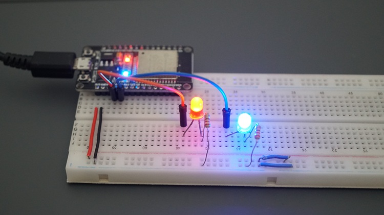
To show you how to do that, we’ll create a new example that blinks two LEDs at different frequencies. We’ll create two periodic timers, one to control each LED.
Circuit Diagram
For this example, connect two LEDs to your ESP32 board via a 220 Ohm resistor. We’re connecting the LEDs to GPIOs 2 and 4, but you can use any other suitable pins. Just make sure to modify the code accordingly.
Parts Required:
- ESP32 board
- 2x LED
- 2x 220 Ohm resistor (or similar values)
- Breadboard
- Jumper wires

Recommended reading: ESP32 Pinout Reference: Which GPIO pins should you use?
Code
Upload the following code to your ESP32 board.
/*
  Rui Santos & Sara Santos - Random Nerd Tutorials
  Complete project details at https://RandomNerdTutorials.com/esp32-freertos-software-timers-interrupts/
  Permission is hereby granted, free of charge, to any person obtaining a copy of this software and associated documentation files.
  The above copyright notice and this permission notice shall be included in all copies or substantial portions of the Software.
*/
#define LED_PIN_RED 2
#define LED_PIN_BLUE 4

TimerHandle_t blinkTimerRed = NULL;
TimerHandle_t blinkTimerBlue = NULL;

bool ledStateRed = false;
bool ledStateBlue = false;

void BlinkRedCallback(TimerHandle_t xTimer) {
  ledStateRed = !ledStateRed;

  if (ledStateRed) {
    digitalWrite(LED_PIN_RED, HIGH);
    Serial.print("Red LED is ");
    Serial.println("ON");
  } else {
    digitalWrite(LED_PIN_RED, LOW);
    Serial.print("Red LED is ");
    Serial.println("OFF");
  }
}

void BlinkBlueCallback(TimerHandle_t xTimer) {
  ledStateBlue = !ledStateBlue;

  if (ledStateBlue) {
    digitalWrite(LED_PIN_BLUE, HIGH);
    Serial.print("Blue LED is ");
    Serial.println("ON");
  } else {
    digitalWrite(LED_PIN_BLUE, LOW);
    Serial.print("Blue LED is ");
    Serial.println("OFF");
  }
}

void setup() {
  Serial.begin(115200);
  delay(1000);
  Serial.println("Starting FreeRTOS");
  Serial.println("Periodic Timers for Two LEDs");

  pinMode(LED_PIN_RED, OUTPUT);
  pinMode(LED_PIN_BLUE, OUTPUT);

  blinkTimerRed = xTimerCreate(
    "BlinkTimerRed",               // Timer name
    700 / portTICK_PERIOD_MS,      // 1s period
    pdTRUE,                        // Auto-reload (periodic timer)
    NULL,                          // Timer ID
    BlinkRedCallback               // Callback function
  );
  if (blinkTimerRed == NULL) {
    Serial.println("Failed to create blinkTimerRed timer!");
    while (1);
  }

  blinkTimerBlue = xTimerCreate(
    "BlinkTimerBlue",               // Timer name
    1100 / portTICK_PERIOD_MS,      // 1s period
    pdTRUE,                         // Auto-reload (periodic timer)
    NULL,                           // Timer ID
    BlinkBlueCallback               // Callback function
  );
  if (blinkTimerBlue == NULL) {
    Serial.println("Failed to create blinkTimerBlue timer!");
    while (1);
  }

  xTimerStart(blinkTimerRed, 0); // Start timer immediately
  xTimerStart(blinkTimerBlue, 0); // Start timer immediately
}

void loop() {
  // Empty
}
How Does the Code Work?
If you’ve understood how to create a timer in the previous example, you’ll see that it is quite simple to create multiple timers.
We define the GPIOs to control each of the LEDs.
#define LED_PIN_RED 2
#define LED_PIN_BLUE 4
Then, we create a time handler for each timer. Each timer will control a different LED.
TimerHandle_t blinkTimerRed = NULL;
TimerHandle_t blinkTimerBlue = NULL;
We create a callback function that will be called after each timer to control each of the LEDs.
void BlinkRedCallback(TimerHandle_t xTimer) {
  ledStateRed = !ledStateRed;

  if (ledStateRed) {
    digitalWrite(LED_PIN_RED, HIGH);
    Serial.print("Red LED is ");
    Serial.println("ON");
  } else {
    digitalWrite(LED_PIN_RED, LOW);
    Serial.print("Red LED is ");
    Serial.println("OFF");
  }
}

void BlinkBlueCallback(TimerHandle_t xTimer) {
  ledStateBlue = !ledStateBlue;

  if (ledStateBlue) {
    digitalWrite(LED_PIN_BLUE, HIGH);
    Serial.print("Blue LED is ");
    Serial.println("ON");
  } else {
    digitalWrite(LED_PIN_BLUE, LOW);
    Serial.print("Blue LED is ");
    Serial.println("OFF");
  }
}
In the setup(), we can actually create the timers to blink each of the LEDs. The following timer will call the BlinkRedCallback function every 700 milliseconds, which will result in the Red LED toggling its state every 700 milliseconds.
blinkTimerRed = xTimerCreate(
  "BlinkTimerRed",                   // Timer name
  700 / portTICK_PERIOD_MS,      // 1s period
  pdTRUE,                         // Auto-reload (periodic timer)
  NULL,                           // Timer ID
  BlinkRedCallback                   // Callback function
);
if (blinkTimerRed == NULL) {
  Serial.println("Failed to create blinkTimerRed timer!");
  while (1);
}
We also create a timer to control the other LED. This timer will call the BlinkBlueCallback function every 1100 milliseconds.
blinkTimerBlue = xTimerCreate(
  "BlinkTimerBlue",                   // Timer name
  1100 / portTICK_PERIOD_MS,      // 1s period
  pdTRUE,                         // Auto-reload (periodic timer)
  NULL,                           // Timer ID
  BlinkBlueCallback                   // Callback function
);
if (blinkTimerBlue == NULL) {
  Serial.println("Failed to create blinkTimerBlue timer!");
  while (1);
}
Finally, we can start the timers by calling the xTimerStart() function.
xTimerStart(blinkTimerRed, 0); // Start timer immediately
xTimerStart(blinkTimerBlue, 0); // Start timer immediately
The loop() is empty because the FreeRTOS scheduler will take care of running the timers at the appropriate time. If you need, you can add code to the loop() for any other tasks you need for your project.
void loop() {
  // Empty
}
Demonstration
Upload the previous code to your ESP32 board.
This will result in two LEDs blinking at different frequencies.
You can also open the Serial Monitor to check the results.

FreeRTOS One-Shot Timers with the ESP32
One-shot timers will trigger a callback function once after a predefined period. This allows you to run a specific task after a predefined time.

1) Toggle an LED with a Pushbutton (with a delay)
To show you how one-shot timers work, we’ll create a simple example in which we’ll toggle the state of an LED five seconds after pressing a pushbutton.
Here’s how it works:
- LED is off.
- Press the pushbutton.
- After 5 seconds, the LED turns on.
- LED stays on.
- Press the pushbutton.
- After 5 seconds, the LED turns off.
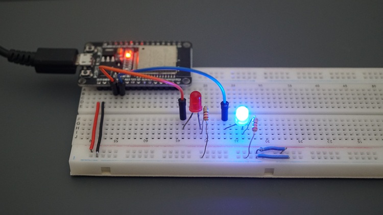
Circuit Diagram
For this example, connect an LED and a pushbutton to the ESP32 GPIOs. We’re connecting the LED to GPIO 2 and the pushbutton to GPIO 4. We’re not using any resistor with the pushbutton because we’ll use the ESP32’s internal pull-up resistor.
Parts Required:
- ESP32 board
- 1x LED
- 1x 220 Ohm resistor (or similar values)
- 1x Pushbutton
- Breadboard
- Jumper wires

Code
Upload the following code to your ESP32 board.
/*
  Rui Santos & Sara Santos - Random Nerd Tutorials
  Complete project details at https://RandomNerdTutorials.com/esp32-freertos-software-timers-interrupts/
  Permission is hereby granted, free of charge, to any person obtaining a copy of this software and associated documentation files.
  The above copyright notice and this permission notice shall be included in all copies or substantial portions of the Software.
*/
#define BUTTON_PIN 4
#define LED_PIN 2
#define DEBOUNCE_DELAY 200
#define TIMER_DELAY 5000

TimerHandle_t toggleTimer = NULL;
volatile uint32_t lastInterruptTime = 0;
volatile bool ledState = false;

void IRAM_ATTR buttonISR() {
  uint32_t currentTime = millis();
  if (currentTime - lastInterruptTime > DEBOUNCE_DELAY) {
    BaseType_t higherPriorityTaskWoken = pdFALSE;
    xTimerStartFromISR(toggleTimer, &higherPriorityTaskWoken);
    Serial.print("buttonISR: LED will ");
    if (ledState) {
      Serial.print("turn OFF");
    } else {
      Serial.print("turn ON");
    }
    Serial.print(" in 5 seconds");
    Serial.println();
    lastInterruptTime = currentTime;
    if (higherPriorityTaskWoken) {
      portYIELD_FROM_ISR();
    }
  }
}

void ToggleCallback(TimerHandle_t xTimer) {
  ledState = !ledState;
  if (ledState) {
    digitalWrite(LED_PIN, HIGH);
    Serial.println("LED is ON");
  } else {
    digitalWrite(LED_PIN, LOW);
    Serial.println("LED is OFF");
  }
}

void setup() {
  Serial.begin(115200);
  delay(1000);
  Serial.println("Starting FreeRTOS");

  pinMode(BUTTON_PIN, INPUT_PULLUP);
  pinMode(LED_PIN, OUTPUT);
  attachInterrupt(digitalPinToInterrupt(BUTTON_PIN), buttonISR, FALLING);

  toggleTimer = xTimerCreate(
    "ToggleTimer",                    // Timer name
    TIMER_DELAY / portTICK_PERIOD_MS, // 5s delay
    pdFALSE,                          // One-shot
    NULL,                             // Timer ID
    ToggleCallback                   // Callback
  );
  if (toggleTimer == NULL) {
    Serial.println("Failed to create timer!");
    while (1);
  }
}

void loop() {
  // Empty
}
How Does the Code Work
Start by defining the GPIOs for the LED and for the pushbutton. We’re using GPIOs 2 and 4, respectively. You can use any other suitable GPIOs.
#define BUTTON_PIN 4
#define LED_PIN 2
Define the debounce delay for the pushbutton in milliseconds.
#define DEBOUNCE_DELAY 200Define the delay time for the one-shot timer (time between pressing the pushbutton and changing the state of the LED).
#define TIMER_DELAY 5000Create a handle for our one-shot timer. We’re calling it toggleTimer.
TimerHandle_t toggleTimer = NULL;Create a variable to check how much time has passed since the last button press (to prevent false positives).
volatile uint32_t lastInterruptTime = 0;Create a variable called ledState to hold the current LED state.
volatile bool ledState = false; // Made volatile for ISR accessIn the setup(), we initialize the serial monitor for debugging purposes.
void setup() {
  Serial.begin(115200);
We set the pushbutton as an input with an internal pull-up resistor.
pinMode(BUTTON_PIN, INPUT_PULLUP);The LED is set as an OUTPUT.
pinMode(LED_PIN, OUTPUT);Then, we set the pushbutton as an interrupt on FALLING edge. When the pushbutton is pressed, it will call the buttonISR function.
attachInterrupt(digitalPinToInterrupt(BUTTON_PIN), buttonISR, FALLING);Creating the One-shot Timer
We create our one-shot timer, toggleTimer, using the xTimerCreate() function. Notice that we have the 5-second delay time (second argument), and that the third argument is pdFALSE, indicating that we want to set a one-shot timer to trigger after 5 seconds of its initialization. As you can see, it’s quite simple to set up a one-shot timer.
In this case, it will call the ToggleCallback function when triggered.
toggleTimer = xTimerCreate(
  "ToggleTimer",                  // Timer name
  TIMER_DELAY / portTICK_PERIOD_MS,  // 5s delay
  pdFALSE,                        // One-shot
  NULL,                           // Timer ID
  ToggleCallback                  // Callback
);
if (toggleTimer == NULL) {
  Serial.println("Failed to create timer!");
  while (1);
}
buttonISR() Function
The ISR (callback function) for the pushbutton is the buttonISR() function. We first check if we have a valid pushbutton press.
void IRAM_ATTR buttonISR() {
  uint32_t currentTime = millis();
  if (currentTime - lastInterruptTime > DEBOUNCE_DELAY) {
Then, we create and set the higherPriorityTaskWoken variable to pdFALSE. This variable tells us whether the ISR operation (in this case, starting a timer) has unblocked a higher-priority task that need to run immediately. It starts as false.
BaseType_t higherPriorityTaskWoken = pdFALSE;Starting the Timer
Then, we start our timer by calling the xTimerStartFromISR function. We pass as arguments the timer handle, toggleTimer, and the address of higherPriorityTaskWoken (&higherPriorityTaskWoken) so FreeRTOS can update the flag if the operation unblocks a higher-priority task (like the timer service task), allowing us to check it next (if (higherPriorityTaskWoken)) and switch to that task right away if needed for real-time responsiveness (portYIELD_FROM_ISR()).
xTimerStartFromISR(toggleTimer, &higherPriorityTaskWoken);By starting our timer, it will run the ToggleCallback function after five seconds (TIMER_DELAY). The ToggleCallback function simply toggles the current state of the LED.
void ToggleCallback(TimerHandle_t xTimer) {
  ledState = !ledState;
  if (ledState) {
    digitalWrite(LED_PIN, HIGH);
    Serial.println("LED is ON");
  } else {
    digitalWrite(LED_PIN, LOW);
    Serial.println("LED is OFF");
  }
}
Demonstration
Upload the code to your ESP32 board.
Open the Serial Monitor at a baud rate of 115200.
Press the pushbutton. On the Serial Monitor, you’ll get the message: “buttonISR: LED will turn ON in 5 seconds“.

And after five seconds, the LED will turn on.

Press the pushbutton again, and after 5 seconds, the LED will turn off.

Wrapping Up
In this tutorial, we’ve taken a look at how to set up and use FreeRTOS software timers with the ESP32 programmed with Arduino IDE. You learned about periodic and one-shot timers.
For more detailed information about software timers, you can check the official documentation.
If you want to learn more about FreeRTOS programming with the ESP32, check-out our other tutorials:
- ESP32 with FreeRTOS (Arduino IDE) – Getting Started: Create Tasks
- ESP32 with FreeRTOS Queues: Inter-Task Communication (Arduino IDE)
- ESP32 with FreeRTOS: Getting Started with Semaphores (Arduino IDE)
Want to learn more about the ESP32? Check out our resources:
- ESP32 with FreeRTOS (Arduino IDE) – Getting Started: Create Tasks
- Learn ESP32 with Arduino IDE (eBook)
- All our ESP32 Projects and Guides
Thanks for reading.


How is it different from Ticker library?
Very interesting and informative article that puts my brain to work. My question, you gave an example of 2 LEDs flashing at different frequencies. Is it possible to create more timers than two? My thoughts are to read 5 humidity sensors that will each control a solenoid valve. Regards Peter Lörne
Hi.
Yes. You can create more than two timers.
Regards,
Sara
Is there an example using the Watchdog Timers?
Hi.
No.
We don’t have any examples for Watchdog timers at the moment.
Regards,
Sara
Hopefully you may have some examples soon.
Thank you!
Hi,
Is that possible that we can modify the FreeRTOSConfig.h file in order to adapte it to our needs, without braking anything? And if so, where do we put it? In our sketch directory?
For example, out of the box the framework only allows to have 10 timers, maybe this number is good enough for many applications:
// original:
#define CONFIG_FREERTOS_TIMER_QUEUE_LENGTH 10
But suppose that I need to use 20:
// mine:
#define CONFIG_FREERTOS_TIMER_QUEUE_LENGTH 20
Another example is the length for the task’s name:
#define CONFIG_FREERTOS_MAX_TASK_NAME_LEN 16
What if I need (or want) the length’s name to be 80?
How dangerous is to modify such file in this kind of scenarios?
It’s worth to mention that you don’t need to reserve 10 KBytes of RAM to blink a LED (even for the examples):
#define CONFIG_FREERTOS_IDLE_TASK_STACKSIZE 1024
Greetings!
Hi.
I haven’t played with the settings of the config file, so I can’t tell.
I think you can modify those parameters without issues, as long as you adjust with realistic values. But, you’ll have to try to find out.
Regards,
Sara
Thanks for this clear tutorial – I’m trying to get to grips with FreeRTOS and it was really useful. Might even buy the eBook!
However I’m confused by the distinction between timer interrupts, which are handled by what you call ‘callback’ functions and hardware interrupts ( a button press in this tutorial) which are handled by ‘Interrupt Service Routines (ISRs)’. The former are defined in the style void fooCallback() but the latter as void IRAM_ATTR fooISR(). Can you comment on the distinction? I know what IRAM_ATTR does, but don’t understand why it isn’t necessary with timer interrupts.
Regards, Robin
Hi.
I’m not sure if I can explain this clearly.
But, basically, FreeRTOS timers are time-based and not executed in a “real” interrupt context. They are basically “regular” functions that run after a timer runs out.
The hardware interrupts are like “real” CPU interrupts. The ISRs must be placed in the internal IRAM, so that the board doesn’t crash in case the flash memory is not accessible at the moment the interrupt occurs.
Regards,
Sara
Thanks for your explanation Sara. I hadn’t properly understood the distinction between timer and hardware interrupts. I confess I didn’t really understand what you meant by a “regular” function at first, but having dug a little deeper since reading your reply I now realise that timers run under a timer daemon which is a standard task (albeit with priority (config_MAX_PRIORITIES – 1) i.e. the highest possible) and are therefore managed by the RTOS scheduler. In contrast, hardware ISRs can’t be pre-empted under any circumstances.
Thanks again and also for for the many other RandomNerd tutorials which (unlike some of other stuff out there) are clear and accurate.
Robin